IranFanAvaran Team Description Paper
Seyyed Vahid Hashemi, Ali Abbasi, Saeed Abdoshshah, Naser Mahmoodi, Hamid Shakeri Sari, Mostafa Aliei, Mahdi Moradinasab
University of Semnan, Department of Engineering, Semnan, Iran; University of Shahed, Department of Electronics, Tehran, Iran; University of Tehran, Department of Engineering, North Karegar st., Tehran, Iran
http://www.semnan.ac.ir · http://www.shahed.ac.ir · http://www.ut.ac.ir · http://www.iranfanavaran.ir
Abstract This paper describes the mechanical and electrical specifications of a fully autonomous Teen size humanoid robot called "Dara" that IranFanAvaran team have designed and constructed it to participate in RoboCup2009 competitions. The main purpose of this project is to build a humanoid robot to simulate the behavior of human and going to use this generation of robots in some special works instead of human.
During this project we tried to implement an efficient and low cost solution for a Teen size humanoid robot's joints using DC Geared motors. To achieve desired response of joints and balancing of the robot the control algorithm is divided to local and global PID algorithms. Perception and control of the robot is performed by operating several processors together.
1 Introduction
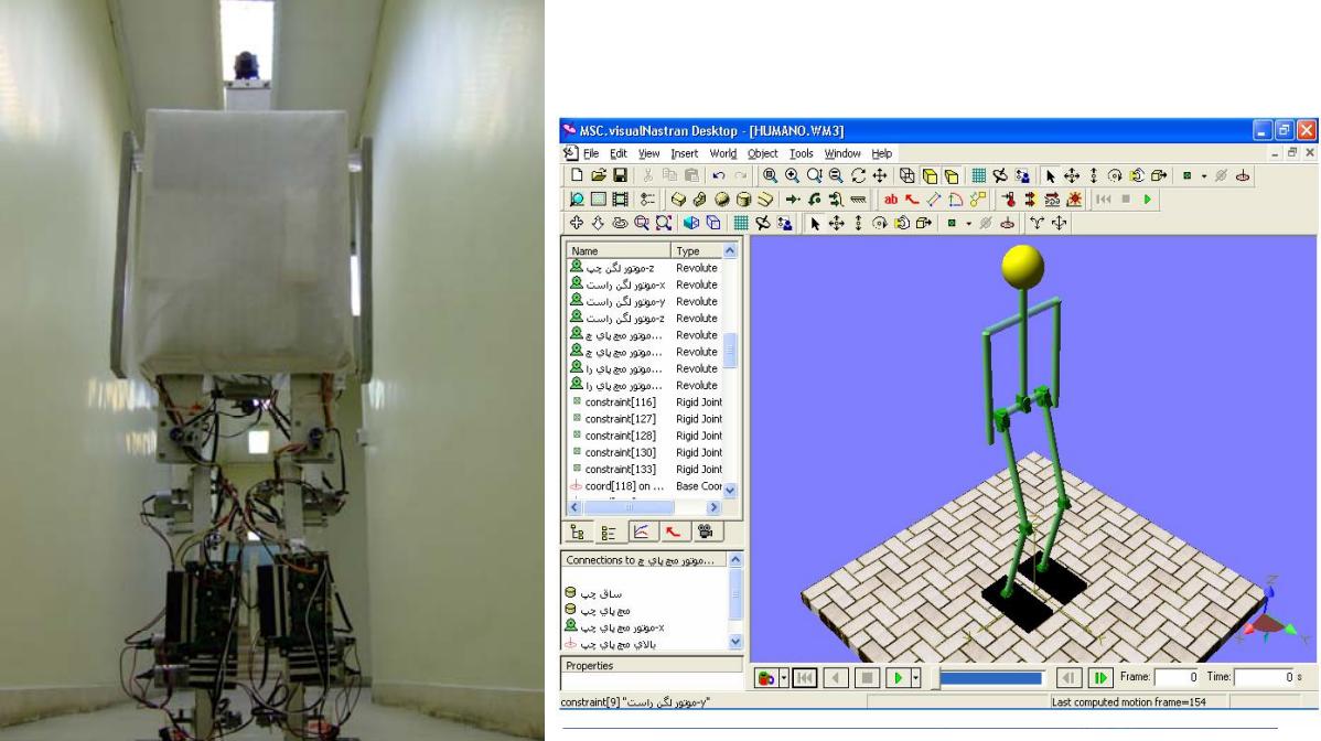
The project was established at University of Semnan in 2003. As this project has been defined, it contains a biped robot with 110cm height that can observe the environment and process it, walk toward a ball and kick it to the goal. During several years we constructed 3 robots. We participated in RoboCup2006 with the second robot. It had some problems that couldn't act well within competitions. But our 3rd robot took 1st place in Iranopen2007, Fig.1 shows our 3rd robot. We tried to construct a new advanced robot and participate in Robocup2008-China but we couldn't find proper sponsor for that event. But this year IRAN ITOK Co. is our sponsor and we are making ready our 4th robot for RoboCup2009 with some differences and developments.
In the remainder of this paper our approach will be mentioned in detail as follows. In the next section we are going to describe the mechanical design and electronics of our robot. Section 3 introduces sensors used in the robot, Section 4 describes the fundamental steps to control the robot, and section 5 explains image processing unit.
2 Dara the Teen Size Humanoid Robot
2.1 Mechanical Design
Robustness was an important parameter that we focused in mechanical design and also the robot is designed regarding to Teen size of RoboCup Soccer humanoid league rules 2009 [1]. This robot has 15 Degrees of Freedom. The height is 110cm and the weight is 9.5kg including batteries. Dara can walk and turn by 12 DC-geared motors which have been converted to Servo. There are six DOFs for each leg on position-wise two DOFs at each hip, one DOF at each knee and two DOFs at each ankle; For theses DOFs we used G35GM-656 product of GIL-Geared Motor and made some changes to increase its torque to 70kg.cm and its speed to 40rpm. Then we converted it to servo and used in robot. Also there are 2 degrees of freedom in shoulders. For these DOFs we don't need high torque actuators. Therefore, we used HS-5245MG servo motors with torque of 5.5 kg.cm @ 6 v. Finally, a HS-65HB Servo motor is used for the neck with torque of 2.2 kg.cm @ 6 v
For Modeling and simulation of the robot we have used Vitual Nastran software; Fig.2 shows a model of the robot in Visual Nastran environment. To build skeleton and attach body parts to each other we used Aluminum extrusions and Plexiglas.
2.2 Electronics
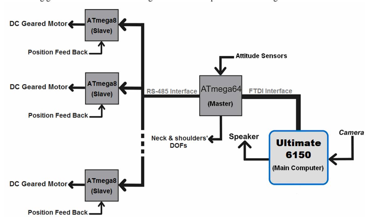
The robot is equipped with a main computer, a 16MIPS ATmega64 AVR microcontroller and several 16MIPS ATmega8 microcontrollers, which each ATmega8 controller is responsible for control algorithm of one degree of freedom and management of converting its DC motor to servo. These ATmega8 controllers are slave in conjunction with the master ATmega64 AVR, the responsible for global balance control algorithm and walking gait of the robot. The block diagram of electronic parts is shown in fig.3.
Slave microcontrollers receive joint angle feedback via potentiometer. After digitizing and calculation of angular speed and acceleration of the joint, they implement PID algorithm.
In addition to the joint sensors, the robot is equipped with attitude sensors, located in the trunk. It consists of a dual-axis accelerometer (ADXL203, ±1.7g) and two gyroscopes (ADXRS 401, ±75◦/s). The sensor signals are received by the master ATmega64 and are used in balance algorithm. Master AVR communicates with Slaves via RS-485 interface at 2MBaud. Also it communicates with the main computer via FTDI interface (USB to Serial converter) at 1MBaud.
The main computer is an Ultimate 6150 Pocket-PC at frequency of 520MHz. This computer is responsible for image processing and perception. It receives image data from its camera and after processing and recognition of proper reaction; it sends related commands to master AVR for execution.
3 Sensors Used
Four types of sensors are used in the robot so that implementation of balance control and perception:
3.1 Vision Sensor
This sensor is the pocket-PC's camera. It receives data from image of around environment of the robot via a wide angle lens to achieve view of 170˚. This sensor is processed by main computer.
3.2 Accelerometer
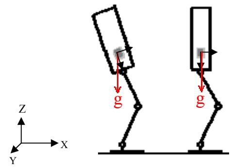
ADXL203 accelerometer detects the gravity vector when robot is static. So the robot can keep the vertical position against the ground (Fig.4). This sensor is useful for static walking algorithm. By its feedback, the robot can walk through rough terrain and also can detect whether it is standing or lying down and therefore the robot can get up automatically. Accelerometer is controlled by master AVR controller.
3.3 Gyro Sensors
There are two ADXRS401 gyro sensors in the robot for lateral and sagittal plans. Each sensor detects angular speed of Center Of Mass of the robot in one axis. They are located as near as possible to COM. Their data help us to specify incorrect behaviors happen during the walking gait.
Accelerometer and gyro sensors are used together for lateral and sagittal planes, which are fused to estimates of the tilt in roll and pitch direction. We use this attitude estimate and its derivative to detect disturbances during walking [2]. These sensors are controlled by master AVR controller.
3.4 Potentiometer
This sensor detects the rotation angle of the actuator. By this sensor, the robot recognizes the current angular position of each joint. And then it's possible to measure angular speed and acceleration of the joint for using in balance control. This sensor is controlled by its related local AVR controller.
4 Control
Balance control of a humanoid robot is one of the fundamental problems. In this way, we need an efficient walking pattern to achieve stability. A walking pattern is statically stable if the center of mass (COM) is in the supporting polygon [3]. Also a walking pattern is dynamically stable if the Zero Moment Point (ZMP) is in the supporting polygon. This pattern can be determined by the hip trajectory and the swing foot trajectory.
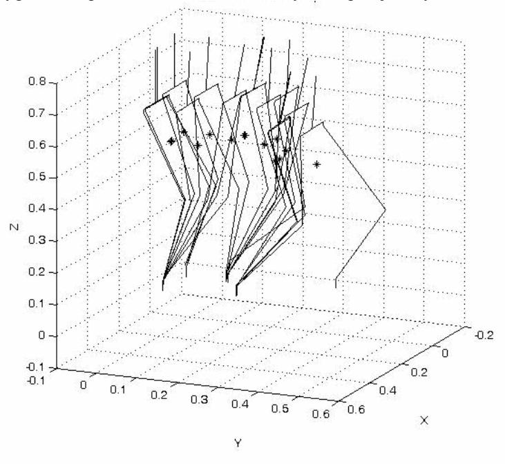
The trajectory of walking of the robot is planned using the angular momentum to ensure that the generated joint trajectories guarantee the dynamic stability of the robot, which usually is quantified by the distance of the zero moment point in the boundaries of a predefined stability region. The position of the zero moment point is affected by the referred mass and inertia of the robot's torso. Fig.5 shows track of the robot in different steps. The controlling algorithms are programmed by Matlab, and the scheme of robot in Visual Nastran is connected to these programs, so we could get some proper data in theory to implement on the real robot and determine the results.
We implemented balance control in two levels. Firstly, the lowest level of control containing digital PID control for DC geared motors used in the joints to achieve the desired angle of the joints. This section is executed with local AVR controllers. Also when a local AVR receives the new position, it implements a local target position generator algorithm [4] to control the average speed, according to the requested speed from the master AVR.
Secondly, the higher level of control is a global PID algorithm that master AVR implements using attitude sensors. Master AVR uses data from accelerometer for static walking. And also it uses angular speeds of COM in lateral and sagittal plans for dynamic walking.
5 Image processing
It is very crucial for a humanoid robot to recognize where it can walk and kick the ball. The image from the camera attached to the top of the robot is processed to identify positions of obstacles as well as any land marks in the field of view.
There are two phases in image processing part. Firstly, color filter and noise-canceller filters are applied for image frames captured from camera. Then the filtered image is processed.
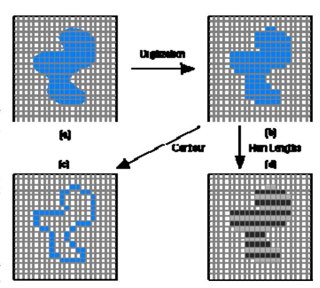
In image processing section, two fundamental algorithms are used: Chain code and SUSAN. When dealing with a region or object, several compact representations is available that can facilitate manipulation and measurements on the object. In each case we assume that we begin with an image representation of the object as shown in Fig.6.
Several techniques exist to represent the region or object by describing its contour. The vision receiver consists of the Pocket-PC's camera, capable of capturing 2Mega pixel frames.
After image processing, the main program uses the outcome to generate a series of motion sequences, which will be sent to the master AVR.
The robot should have correct perception about environment; it must be able to recognize the orange ball and the target. In most cases the robot should react as soon as possible. These reactions consist of moving toward the ball, correction of robot direction, kicking the ball and other reactions.
We implemented image processing algorithms by Visual Basic software.
6 Conclusion
As we described, based on our several years' scientific researches, experiments and experiences, we have designed the 4th generation of Dara, the fully autonomous Teen size humanoid robot.
It has 15 Degrees of Freedom and has new design in mechanism & electronic system as compared to other humanoid robots. We used DC geared motors and we could implement flexible digital PID controller for joints as a low cost and efficient solution.
Now we are making it ready for RoboCup2009 competitions. It is not ready at the moment but according to our plan it will be ready at the end of April 2009.
References
[1] RoboCup Soccer humanoid League Rules and Setup 2009, http://www.tzi.de/humanoid/bin/view/Website/Downloads [2] Reimund Renner and Sven Behnke, "Instability Detection and Fall Avoidance for a Humanoid using Attitude Sensors and Reflexes" in proc. of the 2006 IEEE/RSJ Int. Conf. on Intelligent Robots and Systems. [3] Jacky Baltes, Sara McGrath and John Anderso, "Active Balancing Using Gyroscopes for a Small Humanoid Robot",2nd Int. Conf. on Autonomous Robots and Agents December 13-15, 2004, New Zealand. [4] Jörg Stückler and Sven Behnke, "Soccer Behaviors for Humanoid Robots", In proc. of workshop on humanoid soccer robots of the 2006 IEEE-RAS int. conf. on humanoid robots. [5] Sven Behnke and Raul Rojas, "A hierarchy of reactive behaviors handles complexity",In Balancing Reactivity and Social Deliberation in Multi-Agent Systems, pages 125–136. Springer, 2001. [6] Vermeulen, J., "Trajectory generation for planar hopping and walking robots: An Objective Parameter and Angular Momentum Approach," PHD Thesis, University of Brussel, 2004. [7] F. Dellaert,W. Burgard, D. Fox, and S. Thrun. "Using the condensation algorithm for robust, vision-based mobile robot localization", IEEE Computer Society Conference on Computer Vision and Pattern Recognition (CVPR'99), June 1999. [8] J. Wolf, W. Burgard, and H. Burkhardt. "Robust vision-based localization by combining an image retrieval system with monte carlo localization", IEEE Transactions on Robotics,21(2):208–216, 2005.