Tsinghua Hephaestus 2009 TeenSize Team Description
Mingguo Zhao, Hao Cheng, Wei Chen, Xueyu Ren, Zhiqiang Zhang, Xiaodong Liu
Tsinghua University, Department of Automation, Beijing, China
http://www.au.tsinghua.edu.cn/robotlab/
Abstract This document describes both hardware and software specifications and practical functions of the humanoid robot Stepper_Teen, developed by team Tsinghua Hephaestus as a platform for research in bipedal locomotion, robot self-localization and multi-robot cooperation. The robots will also be used to participate in Humanoid League(TeenSize) of RoboCup 2009 Graz.
1 Introduction
The Tsinghua Hephaestus is a RoboCup Humanoid League team running at Dept. of Automation, Tsinghua University, China, since July 2006. Before that, we had three years' participant experience in RoboCup Full Legged League and got the fifth place in the Technical Challenges in RoboCup2006 Bremen. Our current research interest is focused on bipedal locomotion[1,5], robot self-localization[2,3,4] and multi-robot cooperation in dynamic environment[2]. The humanoid team had taken part in the RoboCup2007 and RoboCup2008 both in KidSize and TeenSize. In the RoboCup2008, our TeenSize team got the 2nd and our KidSize team went into the Round Robin2. We have been getting prepared for the Penalty Kick as well as Technical Challenges for Robocup 2009.
Stepper_Teen is a Teensize humanoid soccer robot developed as a platform for Tsinghua Hephaestus TeenSize team in RoboCup 2008 as well as in RoboCup2009. The main goal is to develop a light weight fast walking soccer robot. A passive dynamic walking based powered walking-Virtual Slope Walking is developed for gait generation and some mechanical refine is ongoing. This document will give a general view of the robot.
2 The Robot Design
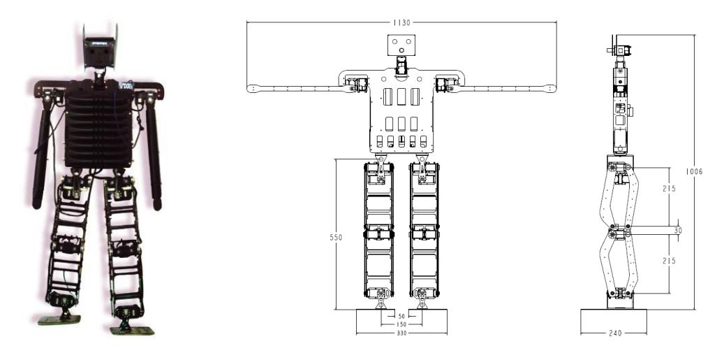
Fig. 2-1 shows one of our Stepper_Teen robots in practice. The robot has a height of 1006 mm, and weights 7.31 Kg, including batteries. The detailed dimensions are shown in Fig. 2-2. The robot has 16 DOFs: 5 in each leg, 2 in each arm, 2 in the head. For Stepper_Teen, Robotics RX-64 servo motors are used as actuators for all DOFs.
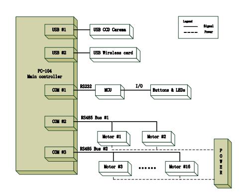
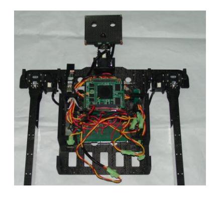
For Stepper_Teen, we use one PC 104 as the main controller, connected with all motors and sensors of the robot by two USB ports and three COM ports (Fig. 2-3). Specifically, one Logitech QuickCam Pro 5000 CCD camera is used to be the vision sensor located in the robot head. Buttons and LEDs , located on the back, are set to control and indicate the robot state, and their signals are processed by the MCU communicated with the main controller via a RS-232 serial line at 19200 Baud. The motors of upper body and lower body are connected in series on a RS-485 bus respectively. The details of the control system are shown in Fig.2-4.
3 Software Architecture
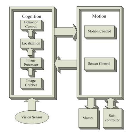
The software architecture consists of two processes, Cognition and Motion. The two processes runs in parallel and interchange data through a message queue. Cognition is responsible for information perception, self-localization and behavior decision, while Motion is responsible of gait planning and motor controlling. Each process is divided into several modules according to functionality. And modules are arranged so that they are independent to each other. Module configurations and data flows are shown in Fig. 3-1.
Image Grabber: grabs images from the vision sensor and generates related information of the image and the pose of the camera.
Image Processor: processes the incoming images grabbed by Image Grabber, and yield information needed for Localization and Behavior Control.
Localization: implements the localization algorithm, manages position information of robots and the ball, as to be used by Behavior Control.
Behavior Control: controls the game process and makes behavior decisions.
Motion Control: manages all the actuators of the robot, and controls locomotion or any other action of the robot according to the requests from Cognition.
Sensor Control: manages other sensors, and interacts with the Sub-Controller.
4 Vision
A Logitech camera is employed as vision sensor. The vision module have two tasks: object recognition and relative position estimation. The object recognition process is based on the result of color segmentation. However, not the whole image is used to retrieve features for object recognition, but the image is scanned along a grid, thus to save computational expense.
4.1 Vision Sensor
The Logitech QuickCam Pro 5000 web camera employed as the vision sensor, which has the field of view is about 51°×37°. The robot has to rotate its head to widen the sight. The connection to t he main controller via USB 2.0 provides Real-time image series of a resolution of 320×240 of 25 fps.
4.2 Color Segmentation
After images are captured, the RGB pixels are mapped to 16 color space simultaneously to minimize the storage cost. The original image (320×240 RGB) would cost about 230KB of RA M resource. With this optimization, this cost would de-crease to 17%.
4.3 Scan line Generalization
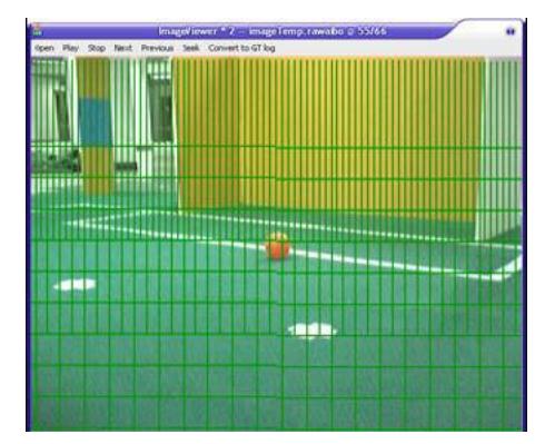
It is not necessary to scan all pixels, but only those on a horizontally aligned grid. The horizon line is calculated based on the pose of the camera. Density of grid lines is proportional to the distance from the horizon line (Fig. 4-1). This optimization practically expedited the respondence of vision module from about 10fps up to more than 15 fps.
4.4 Feature Extraction
Objects are distinguished by colors. As the feature, clusters of different color was extracted along the scan line from top to bottom or left to right. And the process would end if no more "special color" appears. The "special color" found calls further object recognition in related areas. For instance, consecutive orange pixels call the process of ball detector. Single special colored point would not be considered as a target object, in case there was some expected error spot in the image especially during walking or other dynamic situations.
4.5 Object Recognition
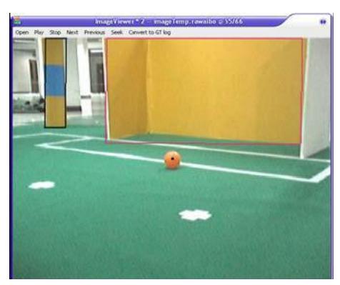
Features, a characteristic series of colors or a pattern of colors, are used for object recognition, e.g., a sequence of some orange pixels is an indication of a ball. Fig. 4-2 shows the recognized ball, goal and beacon in the image.
(1) Ball detector
After roughly calculated the center of ball, edge pixels in vertical, horizontal and both diagonal directions are scanned. Eight edge pixels are used to calculate the precise center and radius of the ball by Levenberg Marquardt method (Curve-fitting algorithm).
(2) Beacons detector
Distance and related position is calculated by yellow and blue pixels along parallel scan lines.
(3) Goal detector
Goal is a reasonably large rectangle area. The goal detector is triggered when 4 consecutive yellow or blue pixels discovered. Because of the scanning sequence, first candidate goal pixel is nearer to its left goalpost. From that, the detector scans along every edge, during which, we alter-nate the direction towards and parallel to the edge. However, if the scan towards the edge doesn't find the edge point, goal detector is suspended immediately.
5 Localization
Table 5-1 outlines the results of our works on localization Module. At present, only the algorithms of self localization using EKF and ball tracking are achieved, the Multi-robot cooperative localization and Collaborative ball localizing and tracking are ongoing.
Table 5-1. Issues of our research
| Achieved Issues | Ongoing Issues |
|---|---|
| Individual robot self localization | Inter-detecting based multi-robot cooperative localization |
| Active localization | Multi-robot cooperative localization using co-detected moving object |
| Individual ball localizing and tracking | Collaborative ball localizing and tracking |
6 Behavior Control
The data provided by the sensors and location module is used to plan a more complex behavior series. And the module of Behavior Control takes the charge of this task. The main task is separated into subtasks until they can be described as a set of basic behaviors which can be executed by the robot. All this is done by a hierarchical state machine described in XABSL (Extensible Agent Behavior Specification Language). The basic motion actions are transferred to and interpreted by the motion module, while other basic actions are processed in further modules.
It can output the following variables:
- 1)A motion request of basic behaviors to inform the motion module the robot's next action.
- 2)A head motion request of head mode to inform the motion module the robot's next head action.
- 3)3 LEDs' state.
An XABSL behavior specification is comprised by a set of behavior modules called options and a set of different simple actions called basic behaviors. Each option consists of numbers of states or subordinate options. Each state has two parts of information, decisions and actions. Decisions describe the conditions whether to jump out or stay in the current state according to the input variable, while the actions consist of the outputs such as the basic behaviors, LEDs etc.
7 Gait Planning
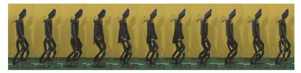
The implementation of forward walking is applying Virtual Slope Walking in the sagittal plane with the Lateral Swing Movement for lateral stability [1]. The sideward walking and turning is realized by carefully designing the key frames. All of the above gait is generated by connecting the key frames with smooth sinusoids.
The forward walking speed of Stepper-Teen is 68cm/s. The image sequences of forward walking are shown in Fig. 7-1.
The image sequences of sideward walking and turning are shown in Fig. 7-2 and Fig. 7-3 respectively.
By merging the translational movements with the rotational movements, Stepper-Teen is able to perform omnidirectional walking.


8 Conclusion
Our TeenSize robot Stepper_Teen is a self-autonomous humanoid robot, with 1 camera and 16 actuators integrated on body, controlled with a PC 104 computer system. In this paper we present the specifications and functions of Stepper_Teen, as well as some related works on vision, localization and gait planning. This year we are going to participate in the Penalty Kick as well as Technical Challenges for Robocup 2009.
References
- Mingguo Zhao, Ji Zhang, Hao Dong, Yu Liu, Liguo Li, and Xuemin Su., "Humanoid Robot Gait Generation Based on Limit Cycle Stability". In the proceedings of the RoboCup Symposium 2008.
- Zhibin Liu, Mingguo Zhao, Zongying Shi, Wenli Xu, Multi-robot Cooperative Localization through Collaborative Visual Object Tracking, Proceedings of RoboCup 2007 Symposium, 2007,Jul., Atlanta, USA.
- CAI Yi-xin, ZHAO Ming-guo, SHI Zong-ying, XU Wen-li, An Exper imenta l Compar ison of Loca liza tion Methods in Robocup Four Legged League[J], Robot 2007 Vol. 29,No. 2, pp167-170.
- Zhibin Liu, Zongying Shi, Mingguo Zhao, Wenli Xu, Mobile Robots Global Localization Using Adaptive Dynamic Clustered Particle Filters[C]. Proceedings of the International Conference on Intelligent Robots and Systems October 29 – Nov 2, 2007 San Diego, CA, USA, pp.1059-1064.
- Hao Dong, Mingguo Zhao, Ji Zhang, Zongying Shi, Naiyao Zhang,Gait Planning of Quadruped Robot Based On Third-Order Spline Interpolation[C],Proceedings of the International Conference on Intelligent Robots and Systems October 9 - 15, 2006, Beijing, China, pp.5756-5761.