NimbRo TeenSize 2010 Team Description
Sven Behnke, Marcell Missura, Michael Schreiber
Rheinische Friedrich-Wilhelms-Universit¨at Bonn Computer Science Institute VI: Autonomous Intelligent Systems, R¨omerstr. 164, 53117 Bonn, Germany
Abstract This document describes the RoboCup Humanoid League team NimbRo TeenSize of Rheinische Friedrich-Wilhelms-Universit¨at Bonn, Germany, as required by the qualification procedure for the competition to be held in Singapore in June 2010.
Our team uses self-constructed robots for playing soccer. The paper describes the mechanical and electrical design of the robots. It also covers the software used for perception and behavior control.
1 Introduction
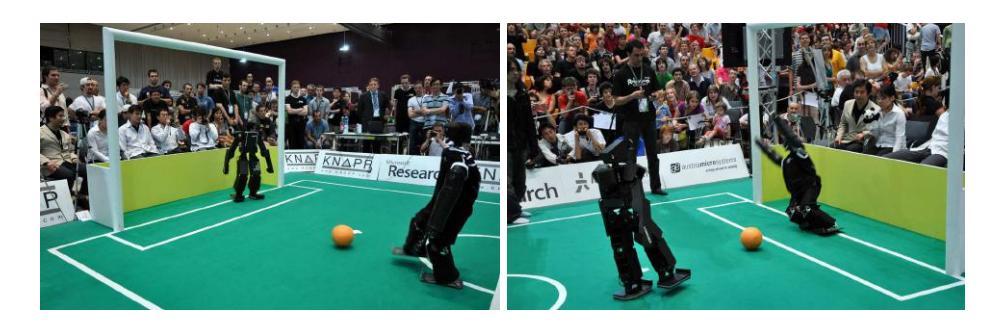
Our TeenSize team participated with success at last year's RoboCup Humanoid League competition in Graz. The robots won the dribble and kick competition and also the technical challenges. Figure 1 shows the final of dribble and kick, where our robots met CIT Brains from Japan. While the robots of both teams were able to find the ball, dribble it, and kick it reliably, only the NimbRo robot Dynaped was also able to quickly jump to the ground as a goalie. It defended the goal successfully against all kicks. Consequently, the game ended 2:0 for NimbRo.
In 2010, the TeenSize class will start to play 2 vs. 2 soccer games. This is a great challenge, as for the first time, TeenSize soccer robots will come close to each other to fight for the ball. This will inevitable lead to falls, which the TeenSize robots must survive. For these soccer games, we will continue to use the NimbRo TeenSize robots Dynaped, Bodo and Robotina. We will also construct new TeenSize robots, which not only survive a fall, but are also able to get-up afterwards. We continuously improve the computer vision and behavior control software.
This document describes the current state of the project as well as the intended development for the RoboCup 2010 competitions. It is organized as follows. In the next section, we describe the mechanical and electrical design of the robots. The perception of the internal robot state and the situation on the field is covered in Sec. 3. The generation of soccer behaviors in a hierarchy of agents and time-scales is explained in Sec. 4.
2 Mechanical and Electrical Design
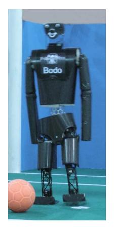
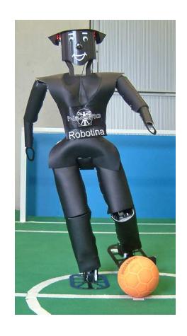
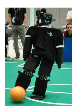
Fig. 2 shows our three TeenSize robots Bodo, Robotina, and Dynaped. As can be seen, the robots have human-like proportions. Their mechanical design focused on simplicity, robustness, and weight reduction.
Bodo is 103cm tall and has a weight of about 5kg. Robotina has a height of 120cm and weighs 9kg. Dynaped is 105cm tall, and weighs 7kg.
Bodo is driven by 14 Dynamixel actuators: 6 per leg and 1 in each arm. For all leg joints, except hip yaw, we use large RX-64 actuators (116g, 64kg·cm). All other joints are driven by smaller DX-117 actuators (66g, 37kg·cm).
Robotina's 23 DOF are driven by a total of 35 Dynamixel actuators. She has 6DOF legs, 4DOF arms, and a 3DOF trunk. All joints in the legs and the trunk, except for the yaw axes, are driven by two parallel actuators. The actuators are coupled in a master-slave configuration. This doubles the torque and lowers operating temperatures. The master-slave pair of actuators has the same interface as the single actuators used for all other joints. Dynamixel RX-64 actuators are used in the legs and DX-117 actuators are used in the trunk and in the arms. The ankle, hip, and trunk yaw/roll axes are reinforced by external 2:1/3:1 spur gears, respectively, resulting in a holding torque of 384kg·cm (39Nm) in the ankle and hip roll joints. The knee is not reduced with an external spur gear, because it needs to move quickly. Instead, a torsional spring is added in parallel to the knee actuators. This spring supports stretching the knee. It is designed to compensate for the weight of the robot when it is standing with partially bent knees.
Dynaped has 12DOF: 5DOF per leg and 1 DOF per arm. Its legs use a parallel kinematics, which keeps the hip parallel to the ground in saggittal direction. The joints are driven by master-slave pairs of EX-106 actuators.
Bodo and Dynaped have a mechanical fuse between the hip and the spine, which allows the robots to jump quickly to the ground as a goalie.
The skeleton of the robots is constructed from aluminum extrusions with rectangular tube cross section. In order to reduce weight, we removed all material not necessary for stability. The feet and other flat parts are made from sheets of carbon composite material. For protection, we included a layer of foal between the outer shell of the robots and their skeleton.
The robots are controlled by an UMPC, a Sony Vaio UX, which features an Intel 1.33GHz ULV Core Solo Processor, 1GB RAM, 32GB SSD, a touchsensitive display, 802.11a/b/g WLAN, and a USB2.0 interface.
The robots are also equipped with a HCS12X microcontroller board, which manages the detailed communication with all joints via an 1Mbaud RS-485 bus. The microcontroller also read in a dual-axis accelerometer and two gyroscopes. This board communicates with the main computer via a RS-232 serial line at 115KBaud. The robots are powered by high-current Lithium-polymer rechargeable batteries, which are located in their lower back and last for about 20min of operation.
3 Perception
Our robots need information about themselves and the situation on the soccer field to act successfully.
3.1 Proprioception
The readings of accelerometers and gyros are fused to estimate the robot's tilt in roll and pitch direction. The gyro bias is automatically calibrated and the lowfrequency components of the tilt estimated from the accelerometers are combined with the integrated turning rates to yield an estimate of the robot's attitude that is insensitive to short linear accelerations. Joint angles, speeds, and loads are also available. Temperatures and voltages are monitored to notify the user in case of overheating or low batteries.
3.2 Computer Vision
We capture and process YUV images. Each pixel is color-classified in a fast multistage process using a color look-up table. In the downsampled color-classified image we detect the ball, the goals, the poles, goal-posts, restart markers, field line features, obstacles, team mates, and opponents by color and size. We estimate distance and angle to each feature in the robot's egocentric coordinate frame by removing radial lens distortion and by inverting the projective mapping from field to image plane. For field line features at corners and T-junctions, we also estimate their orientation relative to the robot.
With limited FOV, parts of the soccer field and the dynamic world state can not be perceived directly. This knowledge has to be inferred and estimated indirectly instead. The goalkeeper, for example, must estimate its pose within the goal through localization using a limited set of visible landmarks. Also, it is valuable to distribute knowledge of the ball position among the players in a team using localization information.
The robot can not perceive its motion directly. Instead, we model its motion based on its gait target velocity. The model accounts for the high noise in its execution. Also, the distance and angle measurements to landmarks are subject to high noise, especially due to inclinations of the robot during walking.
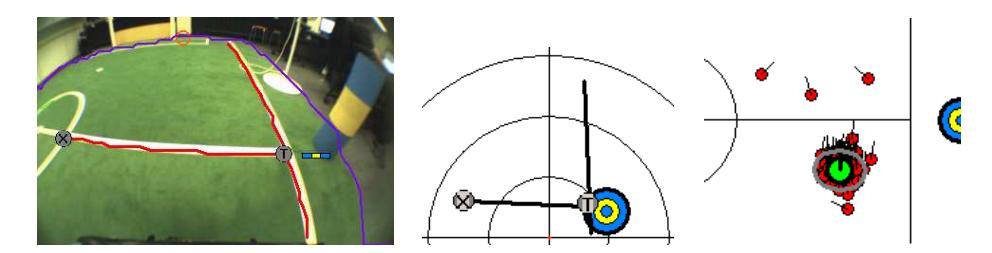
As the goals, the poles, and the goal posts are not sufficient for our localization purposes, we use landmarks like the restart markers, field line corners, and field line T-junctions in addition. However, these landmarks are not uniquely identifiable by color and can not always be identified through geometric constraints in the image.
We estimate the robot's pose on the field by filtering uncertain motion information and landmark observations in a probabilistic way. We use a Monte Carlo localization (MCL) [4] approach, as it can represent multi-modal pose beliefs and can cope with unknown data association. In MCL, the estimate of the current pose of the robot based on previous observations and motion information, $p(s_t|z_{1:t}, u_{1:t})$, is represented with a set of weighted particles. At each time step, the estimate is updated recursively with new motion information and landmark observations. This recursive Bayesian filter is implemented with the Sampling-Importance-Resampling method.
To handle unknown data association of unidentified landmarks in MCL, we sample the data association $c_t$ on a per-particle basis. It indicates the ID of the landmark to which the observation $z_t$ corresponds. For each particle, we sample the association with a likelihood proportionally to the observation likelihood for the landmark in the particle's pose $s_t^{[i]}$, i.e. $c_t \sim \eta \ p(z_t|c_t, s_t^{[i]})$.
The association of field line corner and T-junction observations to landmarks can be improved further. We compare the observed orientation with the expected orientation of the corners and T-junctions in each particle's point of view. By this, these landmark observations become uniquely identifiable in many situations. Our structure-based localization method is illustrated in Fig. 3. Further details can be found in [3].
4 Behavior Control
We control the robots using a framework that supports a hierarchy of reactive behaviors [1]. This framework allows for structured behavior engineering. Multiple layers that run on different time scales contain behaviors of different complexity. When moving up the hierarchy, the speed of sensors, behaviors, and actuators decreases. At the same time, they become more abstract. The framework forces the behavior engineers to define abstract sensors that are aggregated from faster, more basic sensors. Abstract actuators give higher-level behaviors the possibility to configure lower layers in order to eventually influence the state of the world.
The control hierarchy of our robots is arranged in an agent hierarchy, where
- multiple joints (e.g. left knee) constitute a body part (e.g. left leg),
- multiple body parts constitute a player (e.g. field player), and
- multiple players constitute a team.
In this hierarchy, we implemented:
- basic skills (e.g. omnidirectional walking, kicking, getting-up behaviors)
- soccer behaviors (e.g. searching the ball, positioning behind the ball), and
- tactics and team behaviors (e.g. role assignment, player positioning)
Further details on the implemented behaviors have been described by Behnke and Stückler [2].
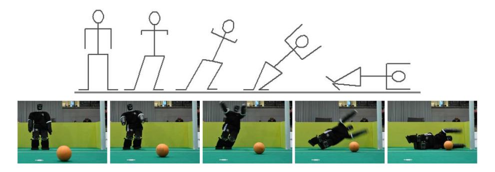
Of special importance in the TeenSize Dibble-and-Kick is the goalie motion. We designed motion sequences that minimize the time to dive from an upright standing posture to the ground. The key phases of this diving motion are depicted in Fig. 4. Further details have been published in [5].
5 Conclusion
At the time of writing, Jan 22nd, 2010, we made good progress in preparation for the competition in Singapore. We will continue to improve the system for RoboCup 2010. The most recent information about our team (including videos) can be found on our web pages www.NimbRo.net.
Acknowledgements
Funding for the project is provided by Deutsche Forschungsgemeinschaft (German Research Foundation, DFG) under grant BE 2556/2 and Rheinische Friedrich-Wilhelms-Universit¨at Bonn.
Team Members
Currently, the NimbRo soccer team has the following members:
- Team leader: Prof. Sven Behnke
- Staff: Marcell Missura and Michael Schreiber
- Students: Andreas Schmitz, Tobias Wilken, and Thomas Windheuser
References
- Sven Behnke and Raul Rojas. A hierarchy of reactive behaviors handles complexity. In Balancing Reactivity and Social Deliberation in Multi-Agent Systems, pages 125–136. Springer, 2001.
- Sven Behnke and J¨org St¨uckler. Hierarchical reactive control for humanoid soccer robots. International Journal of Humanoid Robots (IJHR), 5(3):375–396, 2008.
- Hannes Schulz, Weichao Liu, J¨org St¨uckler, and Sven Behnke. Line structure-based localization for soccer robots. In Proceedings of The 4th Workshop on Humanoid Soccer Robots, International Conference on Humanoid Robots (Humanoids), Paris, 2009.
- S. Thrun, W. Burgard, and D. Fox. Probabilistic Robotics. MIT Press, 2005.
- Tobias Wilken, Marcell Missura, and Sven Behnke. Designing falling motions for a humanoid soccer goalie. In Proceedings of The 4th Workshop on Humanoid Soccer Robots, International Conference on Humanoid Robots (Humanoids), Paris, 2009.