EDROM Humanoid Teen Size 2014
Ana Patrícia Araújo, Caio Ribeiro, Carlos Eduardo Silva, Carolina Resende, Débora Valverde, Igor Bôas, Iuri Souza, Leonardo Jappe, Leonardo Barbosa, Cassiano Moura, Lucas Gonzaga, Mateus Araújo, Murilo Venâncio, Yuri Sousa, Rogério Gonçalves, João Carlos Carvalho
Universidade Federal de Uberlândia, Faculdade de Engenharia Mecânica, Av. João Naves de Ávila 2121, Bloco 1M Uberlândia, Brazil
Abstract This paper describes the development, structure and programming of the robot by the group of students named EDROM, from the University of Uberlândia, Minas Gerais, Brazil. The said robot is going to contest on the Robocup 2014 Humanoid Teen Size category. The main ideas for the robot to accomplish its task are shown following.
1 Introduction
The EDROM (Equipe de Desenvolvimento em Robótica Móvel) was created in 2007. Initially, its main objective was to participate in competitions involving war robots. However, any structure built for this purpose was waste just because of the characteristic objective of this modality: the destruction of the enemy robot. Therefore, the team began investing in research in order to participate in nondestructive modalities. Thus, since 2010 it has participated in robotic competitions, such as LARC, CBR and RoboCup. EDROM already won several titles ever since in various categories like Humanoid Race, SEK and Humanoid Soccer [1].
The EDROM team statement committing to participate in the RoboCup 2014 Humanoid League competition, and making a person with sufficient knowledge of the rules available as referee during the competition.
In this paper were described the steps necessary to achieve the robotic system that will be exhibited in the Teen Size modality on the Robocup 2014. The EDROM first participation in Robocup 2013 was a great experience for all team members on the development and knowledge of methods used to achieve the goal in the modalities in which it participates. Moreover, the learning process due to the difficulties that appeared during the competition triggered a major evolution of the team, thus encouraging further scientific and technical development of more optimized ways now resorted in computer vision and robot movements.
Currently, a quad core APU is used for processing the algorithms that control movement, image recognition and intelligence. Threads were implemented to stratify the activities of the robot and thus achieve a better performance.
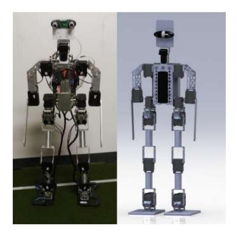
The robot mechanical project was carefully elaborated by one of the team members based on the rules of the competition [2]. SolidWorks was the chosen software to design it. The structure designed is manly made of aluminum.
The robot consists of a camera, servo motors with digital sensors, battery and a friendly user-robot interface composed of keys and LED's. Therefore, the behavior of the robot can be monitored as well as the program inside.
One of the main challenges in the development of teen size humanoid robots is designing joints for the lower body that can produce enough torque to handle the required static and dynamic loads. This is difficult because the actuators for these joints need to be compact enough to be packaged in the constrained space within the robot.
2 Overview
Once the robot has been provided with a quad core processor, all tasks were divided into four threads. The flags thread simplifies the sensors and camera information easing their interpretation by the intelligence thread, it also monitors the states of the robot; the movement thread recovers the robot from the falls, additionally it performs the movements defined by the intelligence function. The camera thread uses the data obtained by the camera then it recognizes the ball and the goalpost.
The camera is capable of capturing 30 frames per second. The APU used is the AMD A4-5000, quad core, Linux operating system, Lubuntu distribution, which was changed to improve its performance; such as withdrawing unnecessary processes for application such as GUI processes and services relating to printing.
3 Hardware specifications
3.1 Controller
The chosen controller is Zodiac ZBOX NANO AQ01 for its high processing power and its capacity to support Linux, which is used along with several libraries, like OpenCV and Open CM9.0.4. The controller has 1.5 GHz, 4 GB memory. As previously mentioned above, the Linux operating system was chosen because of its compatibility with OpenCV and it runs smoothly.
3.2 Camera
The chosen webcam was Minoru 3D, that can easily calculate distances, thus giving the robot a better knowledge of the environment surrounding it.
The camera with two "eyes" also gives the robot a more friendly face, as the competition is also about making the robots human alike.
3.3 Battery
The battery used is a Lithium-Polymer for being lighter than the others with the same capacity, the one that will be used has 4350mAh, 18.5 V.
3.4 Motors
The robot has 18 servomotors: 12 servos MX-106 in the legs, 4 servos MX-64 in the arms and 2 AX-18 in the neck, whose communication is via TTL and RS485.
3.5 Sensor
The sensor that will be used is a Phidget Spatial model 1042, it has a Compass 3- Axis, Gyroscope 3-Axis, Accelerometer 3-Axis. It determines if the robot is falling or has fallen, making it possible to take the necessary action to reverse the situation.
4 Motion
About movements, it was made an inverse kinematic modeling of leg's robot. The purpose of solving the inverse kinematics is to find the angle of each joint for a known foot position. The three-dimensional modeling was divided into twodimensional modeling.
The first one was the side view of the robot, whose inputs are the height of the steps and the position of the foot in front of the robot body. The second was the top view. Combining the two projections, kinematic three-dimensional modeling of the foot was achieved. To simplify the model, the plane of the foot was considered parallel to the floor plane. Besides, the robot body height was considered constant from the floor.
Half period of the sine curve was used both on the front view and on the top as the step curves. The sinusoid was adopted because it resembles the trajectory of the human step.
Its walking algorithms command the trajectory of the feet to follow sine waves in the x, y and z directions. Once the three directional sine waves are combined, the robot begins to walk. The amplitudes and phases are tweaked empirically.
Furthermore, this method was successful because of the relationship between the sinusoidal foot movement and the ZMP (Zero Moment Point) theory [3].
However, the feet trajectories made by only one sinusoidal function are not good enough to make smooth walking pattern. It should be made by combinations of more sinusoidal functions, whose frequencies are two or four times bigger than main sinusoidal function.
This modeling allows changing the geometrical parameters input in order to get the output values for different conditions, among them the value of the forward speed, the direction of the step and the orientation of the robot in the field, considering the mechanical constraints of the robot. Therefore it features an omnidirectional step. Moreover, these parameters can be varied during the execution of the robot controller program enabling control during its movement.
The period parameter of the step was chosen as follow: it was observed that at the end of a period time the modeling step of the robot's body did not return to the proper slope to start the next part of the step. Then the natural frequency of the robot was measured in a mechanical test. A force with variable frequency was applied on the side of the robot to determine which frequency gives maximum energy transfer. Knowing the desired frequency, a control interval of the test was determined; thereafter the number of periods within this interval was taken. Thus, the period corresponding to the natural frequency was identified, which was used as a time parameter of the step.
5 Cumputer Vision
There are many difficulties to deal with problems involving image processing because of the high processing power required. It is a big challenge to develop efficient and low-cost techniques, considering the hardware limitations [4].
Therefore, OpenCV library was used because it is an open source computer vision and machine learning software library, designed for computational efficiency and with a strong focus on real-time applications [5]. In this context, the aim of the robot is to identify certain components in images: ball, goalpost, landmarks and others robots.
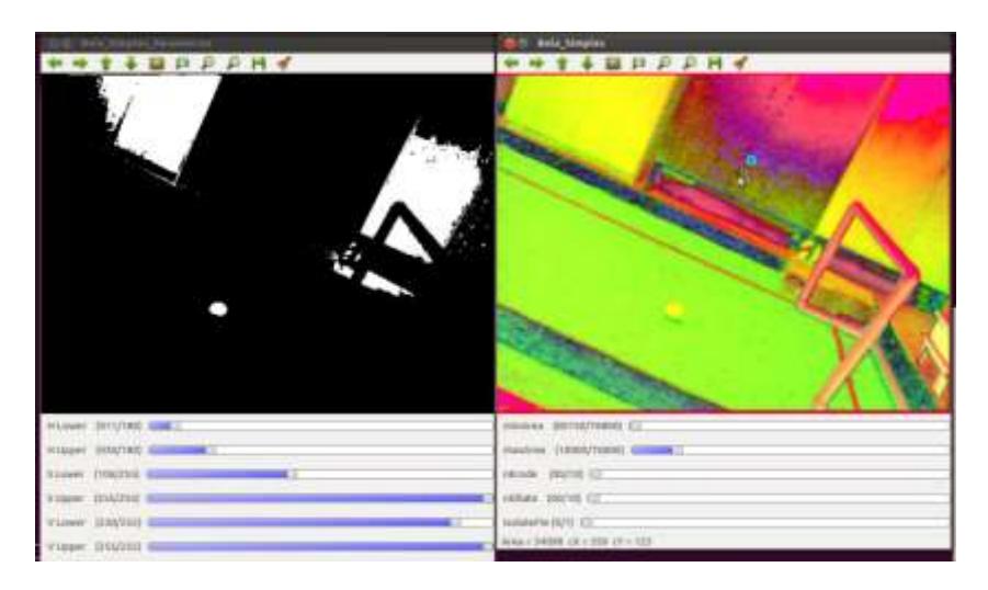
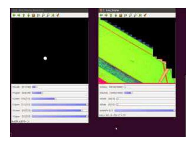
So, the strategy was based on the fact that all these components are always within the limits of the field in the image. Thus, all processing begins by determining the limits of the field, then a region of interest is established and finally external waste components are removed. This was only possible due to low-computational cost routines that give great results. Thereafter, the desired objects are identified in a selected region that is smaller than the original image, reducing the cost of processing and eliminating external elements that could hinder the better performance.
Usually simple operations such as binarization of the images according colors limits, morphological transformations like Dilation and Erosion are enough, but sometimes they are combined with other more advanced algorithms such as the ones for identifying contours and lines (Hough Transform). Algorithms involving histograms and techniques for object tracking have been developed and they are being adapted, improved, and tested in embedded system.
Nevertheless, with the acquisition of new equipment like a more powerful controller and a camera with better resolution and Wide Angle Lens, the team is conducting researches on calibration of cameras, 3D computer vision, histogram algorithms, machine learning and other real-time computer vision tools.
Using the said operations, data about the location of the object relative to the image are obtained. This data must be processed to achieve their locations relative to the robot. This is achieved from the measures previously obtained from robot dimensions, camera specifications and environmental characteristics, properly related to the positions of the head motors and image data.
The team has also been researching the implementation of mapping techniques such as Monte Carlo.
Besides, the information from accelerometer-gyroscope-compass, from the judge and from the others robots are the basis for robot to make decisions and react.
This work was supported by the FEMEC/UFU, FAPEMIG, CNPq and RADIX.
6 Conclusions
This paper presents just a brief description of what was used by EDROM team. There are still a few changes to be made to optimize important functions of the final project. The main goal of this work was to implement a bipedal walking and computational vision method that allows a teen sized humanoid robot to walk and to find the ball and kick it into the goal according to the rules of this competition RoboCup 2014 [2]. It will be a new challenge, because the robot yet to be finished will be very different from the past year.
References
- EDROM <ufuedrom.wordpress.com>
- RoboCup Soccer Humanoid League Rules and Setup for the 2014 competition. http://www.informatik.uni-bremen.de/humanoid/pub/Website/Downloads/HumanoidLeagueRules2014-01-10.pdf
- Bipedal Walking for a Full-sized Humanoid Robot Utilizing Sinusoidal Feet Trajectories and Its Energy Consumption <scholar.lib.vt.edu/theses/available/etd-05042012-155703/unrestricted/Han_Jaekweon_D_2012.pdf>
- OPENCV http://opencv.org/
- Learning OpenCV. 2008. BRADSKI, Gary and KAEHLER, Adrian.