NimbRo TeenSize 2014 Team Description
Marcell Missura, Philipp Allgeuer, Michael Schreiber, Cedrick Münstermann, Max Schwarz, Sebastian Schueller, Sven Behnke
Rheinische Friedrich-Wilhelms-Universität Bonn Computer Science Institute VI: Autonomous Intelligent Systems Friedrich-Ebert-Allee 144, 53113 Bonn, Germany
Abstract This document describes the RoboCup Humanoid League team NimbRo TeenSize of Rheinische Friedrich-Wilhelms-Universität Bonn, Germany, as required by the RoboCup qualification procedure for the competition to be held in João Pessoa in July 2014. Our team uses self-constructed robots for playing soccer. This paper describes the mechanical and electrical design of the robots, covers the software used for perception, motion, and behavior control, and highlights our scientific achievements.
1 Introduction
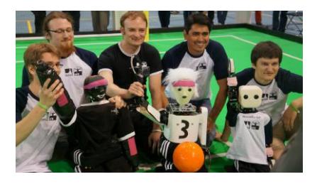
Our TeenSize team participated with great success [7] during last year's RoboCup Humanoid League competition in Eindhoven. Our robots defended their title and won the 2 vs. 2 soccer tournament for the fifth time in row. They also performed well in the Technical Challenge. In 2013, our main innovation was the construction of the the NimbRo-OP [12], a new TeenSize open platform. Our prototype was able to score its first competition goal during the soccer games and it participated in the Technical Challenge. Furthermore, we integrated a compass into our sensor system and solved the disambiguation problem of localization. This year, we will integrate our bipedal gait stabilization concept [5] into our soccer software to significantly improve the robustness of our robots against disturbances during walking. We will also continue to improve the capabilities of the NimbRo-OP and compete with a publicly available open-source version of our soccer software architecture based on the ROS framework.
2 Mechanical and Electrical Design
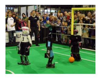
Fig. 1 shows our humanoid TeenSize robots: NimbRo-OP, Copedo, and Dynaped. Their mechanical design is focused on simplicity, robustness, and minimum weight.
2.1 NimbRo-OP
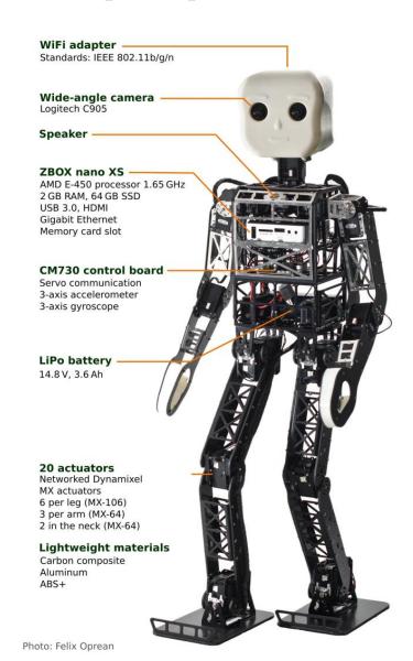
NimbRo-OP [12] is 95 cm tall and weighs 6.6 kg. The robot has 20 degrees of freedom (DoF) altogether, 6 DoF per leg, 3 DoF per arm and 2 DoF in the neck. Limiting the robot size to 95 cm allowed for the use of a single actuator per joint, thus reducing cost and complexity in comparison to our previous TeenSize robots Dynaped and Copedo. We also did not use the parallel kinematic leg design of our previous robots to keep the design as simple as possible.
All joints are driven by intelligent actuators chosen from the Dynamixel MX series manufactured by Robotis. Specifically, MX-106 servos are used in the legs, and MX-64 servos in the arms and neck. All Dynamixel actuators are connected with a single TTL one-wire bus. The servo motors, as well as all the other electronic components can be powered by either a 14.8 V or 11.1 V 3.6 Ah lithium polymer battery. To keep the weight low, light-weight materials like carbon composite and aluminium were used. All material not necessary for stability has been removed. The arms and legs are constructed from milled carbon-composite sheets which are connected with U-shaped aluminium parts cut from sheets and bent on two sides. The torso, which harbors most of the electronic components, is a cage made entirely from aluminium that was cut of a rectangular tube and milled from four sides. The head and the connecting pieces in the hands are 3D printed using ABS+ polymer. The feet are made of flexible carbon composite sheets. The kicking-toes are made of aluminium. NimbRo-OP is equipped with a small Zotac Zbox nano XS PC, capable of running Linux or Windows-based operating systems. This PC features a dual-core AMD E-450 processor with a clock frequency of 1.65 GHz. For data storage, 2 GB RAM (expandable to 4 GB) and a 64 GB solid state disk can be used. A memory card slot is also present. The available communication interfaces are USB 3.0, HDMI, and Gigabit Ethernet. The 10.6×10.6×3.7 cm PC case is embedded within the torso without modification, so that it can be easily upgraded and/or exchanged. The head of the NimbRo-OP contains a small stub antenna that is part of a USB WiFi adapter, which supports IEEE 802.11b/g/n. In addition to the PC, a Robotis CM730 board is used to maintain a high-frequency serial communication link with the servo motors. Furthermore, the CM730 board has an integrated 3-axis accelerometer, gyroscope and magnetometer for attitude estimation. For vision purposes the same Logitech C905 USB camera that Robotis used in the DARwIn-OP was incorporated. We replaced the original lens by a custom wide-angle lens however, that allows the robot to have a field-of-view of up to 180°. The wide visual range resembles the human field-of-view and allows the robot to keep more objects of interest in sight simultaneously, but it also introduces an image distortion that requires correction. Please see Section 3.2 for more details on how this is accounted for.
2.2 Copedo and Dynaped
Copedo is 114 cm tall and weighs 8 kg. Its body design is derived from its predecessor Dynaped, including the 5-DoF legs with parallel kinematics and the spring-loaded passive joint between the hip and the spine. Copedo, however, is equipped with an additional passive joint in the neck to protect the head. Our new generation of protective joints are able to snap back into position automatically after being displaced by mechanical stress. Copedo is constructed from milled carbon fiber parts that are assembled into rectangular shaped legs, and flat arms. The torso is constructed entirely from aluminium and consists of a cylindrical tube that contains the hip-spine spring and a rectangular cage that holds the information processing devices. For protection, a layer of foam was included between the outer shell and the skeleton. Most importantly, Copedo is equipped with 3-DoF arms that include elbow joints to enable the robot to stand up from the ground, to pick up the ball from the floor, and to perform the throw-in motion. Including a neck joint to pan the head, Copedo has 17 actuated DoF. The hip roll, hip pitch, and knee DoF are actuated by master-slave pairs of Dynamixel EX-106+ servo motors. All other DoFs are driven by single motors. The size and weight of Dynaped is 105 cm and 7 kg, respectively. The robot has 13 DoF: 5 DoF per leg, 1 DoF per arm, and 1 DoF in the neck. It also uses parallel kinematics with pairs of EX-106 actuators. Due to a flexible shoulder joint socketed on rubber struts and the passive protective joint in the spine, Dynaped is capable of performing a goalie jump. Both Dynaped and Copedo are controlled by a small PC, which features an Intel 1.33 GHz processor and a touch screen. A HCS12X microcontroller board manages the detailed communication with all joints via a 1 Mbaud RS-485 bus. The microcontroller also reads in a dual-axis accelerometer and two gyroscopes.
3 Perception
Our robots need information about their internal state and the situation on the soccer field to act successfully.
3.1 Proprioception
An estimate of the torso attitude is formed based on the sensory data, using a nonlinear passive complementary filter as described by Mahony et al. [4]. This attitude estimation is combined with the joint angle feedback of the servos to obtain a high-level pose estimation using a kinematic model. First, we apply the joint angles to the model using forward kinematics and then we rotate the entire model around the current support foot such that the torso attitude matches our formed attitude estimate. This way, we obtain a robot pose approximation that can be used to extract the location and velocity of the center of mass. We assume that the support foot is the one that has a lower coordinate with respect to the vertical world axis of the rotated kinematic model. Temperatures and voltages are also monitored for notification of overheating or low batteries.
3.2 Computer Vision
For visual perception of the game situation, we process wide-angle YUV images from a Logitech C905 (NimbRo-OP) or an IDS uEye camera (Copedo and Dynaped) fitted with a fisheye lens. Pixels are color-classified using a look-up table. In down-sampled images of the individual colors, we detect the ball, goalposts, poles, penalty markers, field lines, corners, T-junctions, X-crossings, obstacles, team mates, and opponents utilizing color, size and shape information. We estimate distance and angle to each detected object by inverting the projective mapping from the field to the image plane. To account for camera pose changes during walking, we learned a direct mapping from the IMU readings to offsets in the image. We also determine the orientation of lines, corners and T-junctions relative to the robot.
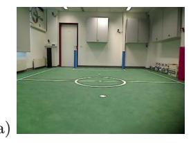
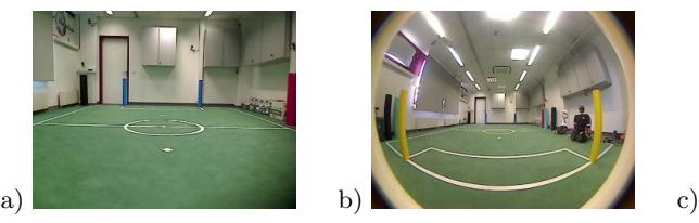
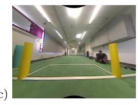
While our wide-angle lens cameras allow the robot to have a human-like field of view of up to 180° and allow the robots to keep more objects of interest in sight, it also introduces an image distortion as shown in Figure 2. To implement a correction algorithm, a detailed distortion model was implemented, akin to the one used by OpenCV. Both radial and tangential distortions are modeled. The transformation model of a point (x, y, z) from camera frame coordinates to image coordinates (u, v) is summarized by the following equations. The k₁₋₆ parameters are the radial distortion coefficients, the p₁₋₂ parameters are the tangential distortion coefficients, and fx, fy, cˣ and cʸ are the camera parameters.
$$x' = \frac{x}{z}, \quad y' = \frac{y}{z}$$
$$r^2 = x'^2 + y'^2$$
$$x'' = \left(\frac{1 + k_1 r^2 + k_2 r^4 + k_3 r^6}{1 + k_4 r^2 + k_5 r^4 + k_6 r^6}\right) x' + 2p_1 x' y' + p_2 (r^2 + 2x'^2)$$
$$y'' = \left(\frac{1 + k_1 r^2 + k_2 r^4 + k_3 r^6}{1 + k_4 r^2 + k_5 r^4 + k_6 r^6}\right) y' + 2p_2 x' y' + p_1 (r^2 + 2y'^2)$$
$$u = f_x x'' + c_x$$
$$v = f_y y'' + c_y$$
The inverse transformation is performed using numerical methods.
3.3 Localization
For localization, we track a three-dimensional robot pose (x, y, θ) on the field using a particle filter [14]. The particles are updated using a linear motion model. Its parameters are learned from motion capture data [10]. The weights of the particles are updated according to a probabilistic model of landmark observations (distance and angle) that accounts for measurement noise. To handle unknown data association of ambiguous landmarks, we sample the data association on a per-particle basis. The association of field line corner and T-junction observations is simplified using the orientation of these landmarks. By utilizing field line-based landmarks, their orientations, and a compass, we are able to reliably track and disambiguate the robot pose without the use of colored landmarks. Further details can be found in [11] and [3].
4 Behavior Control
We control our robots using a layered framework that supports a hierarchy of reactive behaviors [1] [2]. Multiple layers that run on different time scales contain behaviors at different abstraction levels. When moving up the hierarchy, the update frequency of sensors, behaviors, and actuators decreases. At the same time, they become more abstract. Raw sensor input from the lower layers is aggregated to slower, abstract sensors in the higher layers. Abstract actuators enable higher-level behaviors to configure lower layers in order to eventually influence the state of the world. Currently, our implementation consists of three layers. The lowest, fastest layer is responsible for a fall protection reflex, that relaxes all joints when an inevitable fall is detected by the attitude sensors, and generating motions, such as walking, kicking, getting up, and the goalie dive. Our central pattern generated omnidirectional gait [6] is based on rhythmic lateral weight shifts and coordinated swinging of the non-support leg in the walking direction. For the goalie, we designed a motion sequence that accelerates the diving motion compared to passive sideways falling from an upright standing posture [9]. The goalie jump decision is based on a support vector machine that was trained with real ball observations. Get-up motions are designed using a simple, linear interpolated keyframe technique [13]. They are executed openloop when a prone or supine position is detected. At the next layer, we abstract from the complex kinematic chain, and model the robot as a simple holonomic point mass that is controlled with a desired velocity in sagittal, lateral and rotational directions. We use a cascade of reactive behaviors based on a force field method to generate ball approach and dribbling trajectories with integrated obstacle avoidance. This abstraction layer is also used to implement a pushresistant omnidirectional capture step controller [5] that enables the robot to quickly react to disturbances and maintain its balance during walking. Based on the point mass abstraction, suitable footstep locations and step timings are computed on the fly and are executed using the open-loop gait engine in the bottom layer. Our balance controller is outlined in more detail in Section 5.
The topmost layer of our framework takes care of team behavior, game tactics and the implementation of the game states as commanded by the referee box.
5 Robust Omnidirectional Walking
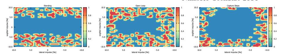
In recent years, team NimbRo has developed a gait control framework capable of recovering from pushes that are strong enough to force a bipedal walker to adjust step-timing and foot-placement. The lateral balance mechanisms [8] have already been used in competitions. Now however, the framework is able to absorb pushes from any direction at any time during the gait cycle [5]. In brief, the Capture Step Framework is based on a simplified state representation in the form of a point mass that is assumed to behave like a linear inverted pendulum. A decomposition of the lateral and sagittal dimensions into independent entities, and a sequential computation of step-timing, zero-moment point and foot-placement control parameters facilitates the closed-form mathematical formulation of a balance controller.
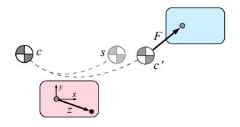
The computations inside the balance control module begin with the input of the current state c = (cₓ, ċₓ, cᵧ, ċᵧ) of the center of mass and a desired end-ofstep state s. The current state includes the sagittal and lateral CoM locations and velocities with respect to the support foot, as they have been measured by the sensors of the robot. The target state s is inferred from the walking velocity input from a higher layer. Figure 3 illustrates a typical situation during a step.
Acknowledgements
This research is supported by Deutsche Forschungsgemeinschaft (German Research Foundation, DFG) under grant BE 2556/6.
Team Members
Currently, the NimbRo soccer team has the following members:
- Team leader: Sven Behnke
- Members: Marcell Missura, Philipp Allgeuer, Michael Schreiber, Cedrick Münstermann, Max Schwarz, and Sebastian Schueller
Team NimbRo commits to participating in RoboCup 2014 in João Pessoa and to provide a referee knowledgeable of the rules of the Humanoid League.
References
- Philipp Allgeuer and Sven Behnke. Hierarchical and state-based architectures for robot behavior planning and control. In Proceedings of 8th Workshop on Humanoid Soccer Robots, IEEE-RAS Int. Conf. on Humanoid Robots, Atlanta, USA, 2013.
- Sven Behnke and Jörg Stückler. Hierarchical reactive control for humanoid soccer robots. International Journal of Humanoid Robots (IJHR), 5(3):375–396, 2008.
- Daniel D. Lee, Seung-Joon Yi, Stephen G. McGill, Yida Zhang, Sven Behnke, Marcell Missura, Hannes Schulz, Dennis Hong, Jeakweon Han, and Michael Hopkins. RoboCup 2011 Humanoid League winners. In RoboCup 2011: Robot Soccer World Cup XV, volume 7416 of LNCS, pages 37–50. Springer, 2012.
- Robert Mahony, Tarek Hamel, and Jean-Michel Pflimlin. Nonlinear complementary filters on the special orthogonal group. IEEE Transactions on Automatic Control, 53(5):1203–1218, 2008.
- M. Missura and S. Behnke. Omnidirectional capture steps for bipedal walking. In Proceedings of IEEE Int. Conf. on Humanoid Robots (Humanoids), 2013.
- M. Missura and S. Behnke. Self-stable Omnidirectional Walking with Compliant Joints. In Proceedings of 8th Workshop on Humanoid Soccer Robots, IEEE Int. Conf. on Humanoid Robots, Atlanta, USA, 2013.
- M. Missura, C. Münstermann, P. Allgeuer, M. Schwarz, J. Pastrana, S. Schueller, M. Schreiber, and S. Behnke. Learning to improve capture steps for disturbance rejection in humanoid soccer. In RoboCup 2013: Robot Soccer World Cup XVII, pages 56–67. Springer, 2014.
- Marcell Missura and Sven Behnke. Lateral capture steps for bipedal walking. In Proceedings of 11th IEEE-RAS International Conference on Humanoid Robots (Humanoids), Bled, Slovenia, pages 401–408, 2011.
- Marcell Missura, Tobias Wilken, and Sven Behnke. Designing effective humanoid soccer goalies. In RoboCup 2010: Robot Soccer World Cup XIV, volume 6556 of LNCS, pages 374–385. Springer, 2011.
- Andreas Schmitz, Marcell Missura, and Sven Behnke. Learning footstep prediction from motion capture. In RoboCup 2010: Robot Soccer World Cup XIV, volume 6556 of LNCS, pages 97–108. Springer, 2011.
- H. Schulz and S. Behnke. Utilizing the structure of field lines for efficient soccer robot localization. Advanced Robotics, 26:1603–1621, 2012.
- Max Schwarz, Michael Schreiber, Sebastian Schueller, Marcell Missura, and Sven Behnke. NimbRo-OP humanoid teensize open platform. In In Proceedings of 7th Workshop on Humanoid Soccer Robots, IEEE-RAS International Conference on Humanoid Robots, Osaka, 2012.
- J. Stückler, J. Schwenk, and S. Behnke. Getting back on two feet: Reliable standingup routines for a humanoid robot. In Proceedings of The 9th International Conference on Intelligent Autonomous Systems (IAS-9), 2006.
- S. Thrun, W. Burgard, and D. Fox. Probabilistic Robotics. MIT Press, 2005.