AcYut TeenSize Team Description Paper 2017
Anant Anurag, Archit Jain, Vikram Nitin, Aadi Jain, Sarvesh Srinivasan, Shivam Roy, Anuvind Bhat, Dhaivata Pandya, Bijoy Kumar Rout
Centre for Robotics and Intelligent Systems, Birla Institute of Technology and Science, Pilani. Rajasthan 333031, India
Abstract This paper summarizes the developments in humanoid robotics by Team AcYut of Birla Institute of Technology and Science, Pilani. This paper is submitted as a prerequisite for participation in TeenSize Humanoid Soccer League, RoboCup 2017 to be held in Nagoya, Japan. All robots have been developed exclusively by the team. This paper describes the hardware design of our humanoids and the underlying software in its autonomous nature.
Introduction
AcYut is a series of humanoid robots developed by undergraduate students of Birla Institute of Technology and Science, Pilani. The aim of the project is the development of a humanoid robot that has practical applications. Our team made its first humanoid robot, AcYut 1, in 2008 which was first of its kind in India. After AcYut 1, the team built a stronger, taller and better version of the robot, AcYut 2. AcYut 2 was semi-autonomous and could be controlled remotely. It was then upgraded to AcYut 3, having superior computing power enabling implementation of advanced algorithms. AcYut 4 was developed as a design upgrade to its predecessor. AcYut 4 was also the team's first entry to RoboCup in 2011. It stood the third in position in the TeenSize Humanoid category.
The team has also won other accolades, some of the notable ones being Gold and Silver medals in humanoid Sumo wrestling at RoboGames 2010 and world record for the most weight lifted by a large humanoid (40 CDs) at FIRA 2010, held at Bangalore in September 2010. The team subsequently participated with the humanoid AcYut 5, in RoboCup 2013 at Eindhoven, Netherlands where we stood 4th in the humanoid teen size league category.
Recent developments
Team AcYut participated in RoboCup2015 in Hefei, China and was placed 6th in the TeenSize Humanoid Soccer category. Since then the team have improved our design and software. We have also published 2 papers in the last year, on path planning [3] and image processing [4].
Mechanical Design
(section header only)
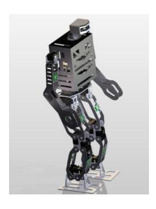
AcYut 8
AcYut 8 has 18 degrees of freedom distributed as follows: 5 in each leg, 3 in each arms, 2 in the head. Dynamxiel MX 106, 64, 28 have been used in the legs, arms and neck as per the varying necessary torque requirements. Light weight Carbon Fiber (CFRP) brackets are linked to actuators housed in Aluminum 6061-T6 frames throughout the design, which significantly reduces the weight of the robot while providing high structural rigidity and strength. A layered CFRP torso houses the NUC, IMU, battery and wiring of the entire robot. The height of the robot is 88cm and weighs 5.9 kg. Top speed of walking is 22 cm/s.
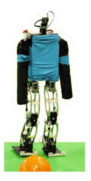
AcYut 7
AcYut 7 has 18 degrees of freedom distributed as follows: 5 in each leg, 3 in each arms, 2 in the head. Dynamxiel EX 106 has been used in the legs and MX 64 has been used in the arms and neck. Aluminium brackets are linked to actuators housed in Aluminum 6061-T6 frames throughout the design, which are designed to reduce weight of the robot while providing high structural rigidity and strength. The height of the robot is 99 cm and weighs 7.1 kg. Top speed of walking is 15 cm/s.
Electrical System
The processing requirements of the humanoid are met by an Intel i3-4010U processor, which is connected to the camera, IMU, and controller board for actuators. Wireless communication with the processor has been established. The processor is powered by a Lithium Polymer battery with regulated voltage. The voltage supplied to all motors are likewise regulated to accommodate voltage fluctuations. The IMU is used to localize the robot using yaw angle to determine the present heading, and to stabilize it by detecting disturbances using the roll and pitch angles.
The following discrete components have been used in the robots.
- Active Sensors (a) Camera 1: iDS UI-1221LE-C-HQ (752x480 CMOS color) (b) Camera 2: PointGrey Firefly MV (640x480 CMOS Color) (c) Camera 3: SonyPlaystation Eye (d) IMU : Pixhawk PX4FMU
- Processor : Intel NUC D34010WYKH
- Batteries : Lithium Polymer 14.8 V 3300mAh
An independent USB based controller board is the interface between processor and actuators and low-level onboard controls. Wireless communication to the Game Controller uses Wi-Fi adapter inside the processor.
Software and Algorithms
(section header only)
Behaviour
The behaviour module is transfers information across different modules and incorporates fail-safe mechanisms to accommodate the crash or inaccuracy of any module. The image processing module may fail to locate the ball or the goal post. In such a scenario, the behaviour framework will supply last locations of the same to the path module so that a path can be generated. Since such processes occur on a frame-by-frame basis, errors introduced by such mechanisms are easily corrected later.
Another crucial function of the behaviour module is to maintain a current global position of the robot. It achieves this by using a motion model implementation which is charted out in Figure 3. The localization module forwards the present global location with an associated confidence. Similarly, the walk module maintains a constantly updated current position estimate which also has an associated confidence derived from the accuracy of the walk of the robot. This confidence decays exponentially with time, and the model is refreshed whenever the robot localizes with high confidence. In case the localization module reports a low confidence value, the motion model framework looks to the walk position estimate for the current position. In some cases it uses a weighted average of the two. It then forwards the current position to the path planning module. The underlying framework [1] also implements inter-system coordination.
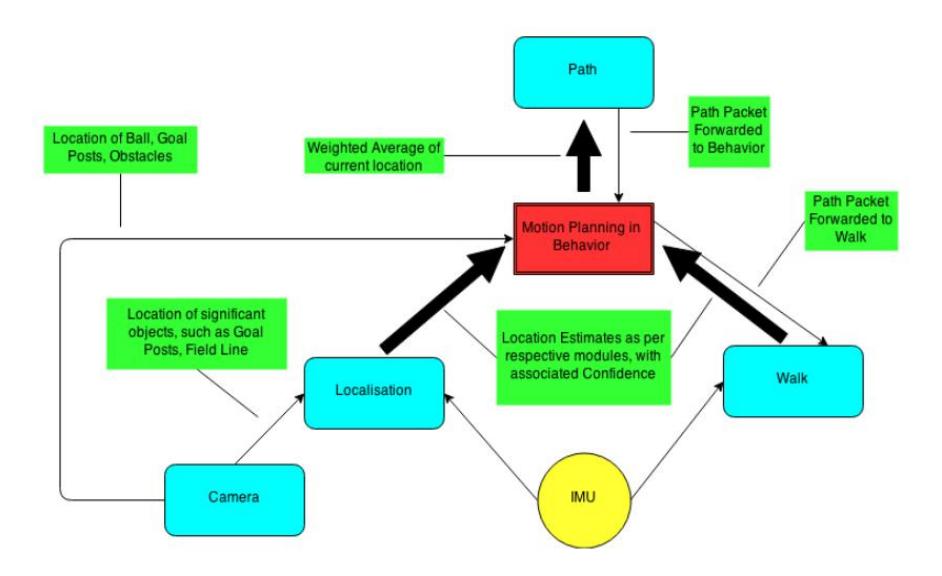
Image Processing
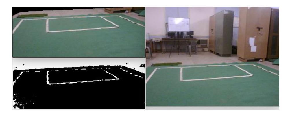
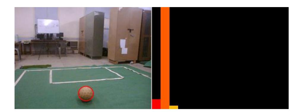
For field detection, convex hulls of green color are chosen, ranked, and merged if in close proximity, to overcome the division of the field into different parts by field lines. For feature detection like the ball we use histogram-based methods to track each object, taking advantage of the fact that certain objects have a well-defined histogram which is easily distinguishable against the green field. The distances of field lines from the robot is calculated using Inverse Perspective Mapping. This data is forwarded to localization for computing the global position of the robot.
Localization
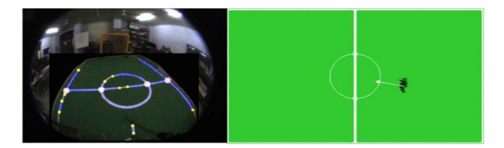
This module deals with the image acquisition from the camera and detection of features for the localization of the robot in the field. Features are defined as elements relevant for regional localization. Examples of features might be the ball, field lines, their intersections, opponents, and teammates. We have used Monte Carlo Localization (MCL) for estimating the 3D pose of our robots. The pose is a tuple (x, y, θ), where (x, y) is the position of the robot in the field in Cartesian coordinates and θ is the orientation of the robot. The particle filter is updated at each frame using the Bayes' theorem based on the combination of beliefs of both the motion model and the observation model. The motion model denotes the probability that the robot is in state xt given that the robot executes an action at in state xt-1 and is updated at each frame by the walk module. The observation model is the likelihood that the robot makes observations zt given that the robot is in state xt.
Path Generation
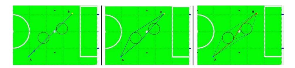
After localizing the ball, goal posts and obstacles, the path generation module is used to find the best possible path to the ball. The path is generated using a geometry based approach which provides quick and accurate results [3]. The generated path is composed entirely of line segments and circular arcs, with obstacles modeled as circles. The path cost is a function of the path length with different weights for the circular and linear proportions of the path.
Gait Generation and Balance
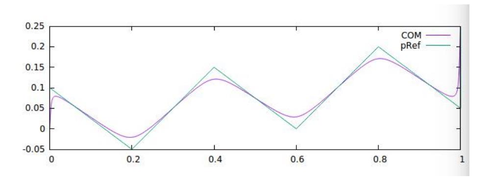
Zero-Moment Point based walking pattern generation is used to create the trajectory [2]. Each step consists of a single-support phase and a double-support phase. The coordinates of the foot placements are provided as inputs to the algorithm, along with the step duration and the height of the plane on which we constrain the COM to move along. Figure 8 is an example of a trajectory generated for a diagonal walk of 6 steps. The X axis is the direction of motion of the robot, and the Y axis is the lateral direction. The trajectory is converted into a vector of motor angles at each time slice, using Inverse Kinematics. The swing leg trajectory is computed from a linear interpolation between the previous and next touchdown positions. Formerly, the team used a 3-D Linear Inverted Pendulum based pattern generation.
Team Members
Team AcYut commits to participating in RoboCup 2017 in Nagoya, Japan and to provide a referee knowledgeable of the rules of the Humanoid League.
Team AcYut comprises of the following members this year:
Team Leader: Anant Anurag
Team Members: Archit Jain, Vikram Nitin, Aadi Jain, Sarvesh Srinivasan, Shivam Roy, Anuvind Bhat and Dhaivata Pandya
References
- Philipp Allgeuer and Sven Behnke: Hierarchical and State-based Architectures for Robot Behavior Planning and Control In: Proceedings of 8th Workshop on Humanoid Soccer Robots, IEEE-RAS Int. Conference on Humanoid Robots. Atlanta, USA (2013)
- Shuuji Kajita et all Biped Walking Pattern Generation by using Preview Control of Zero-Moment Point. In the proceedings of the 2003 IEEE International Conference on Robotics and Automation, Taipei (2003)
- Kaustubh Nawade and V. Aditya: Geometrical approach to On line Trajectory generation, Obstacle avoidance and Footstep planning for a Humanoid Robot. In the 15th IEEE-RAS International Conference on Humanoid Robotics (Humanoids 2015)
- Pratyush Kar and Archit Jain: Effective localization of humanoid with fish-eye lens using field line detection. In Intelligent Robot Systems (ACIRS), Asia-Pacific Conference(2016)