T-FLoW TEAM — Team Description for Humanoid Teen League of RoboCup 2017
Dadet Pramadihanto, Eko Henfri Binugroho, Ahmad Subhan Khalilullah, Dimas Pristovani, Ardiansyah Al-Farouq, Rimsyah Anjar lestiawan, Muhammad Rindo Wardhana, Anas Abdulloh Zaini, Naufal Suryanto, Ajir, Yasinta Musa Dewi
EEPIS Robotic Research Center (ER2C) Politeknik Elektronika Negeri Surabaya (PENS); Kampus Politeknik Elektronika Negeri Surabaya, Jl Raya Kampus ITS Keputih Sukolilo Surabaya, 60111 Jawa Timur Indonesia
Abstract this paper we describe the achievement of humanoid robot research T-Flow to join the RoboCup humanoid Legue 2017 teen size.Kinematics of the robot system T-Flow use Full body kinematic equation. Forward kinematic and inverse kinematic used on any part of the robot is to simplify the design of the path Trajectory planing. The amount of the joint which is almost close to humans to Trajectory planing, especially on the trajectory plan, heads, arms, waist, hip, and leg.so the movement motion that will create a more flexible and closer to human behavior. Robot vision system using stereo camera. The stereo camera can get the information of color, shape, and depth of objects. The third merger such information then the object can be segmented properly.The result is a robot can run the challage at the RoboCup humanoid Legue 2017.
Introduction
T-Flow is competing for the first time in RoboCup 2017. Research and development that has been achieved is to the goal of the international RoboCup Initiative is to Develop a team of humanoid robots that is able to win againts the official human Word Soccer Chmpion team until 2050[1] . Design mechanical robot T-Flow refers to the many normal human joint that allows adapted. on the head using 3 Dof to allow the head can move freely as desired and as an external stabilizer that occurs due to the external disturbance caused by the body. At the waist using 3 Dof to allow passage waist move freely allowing it to maintain the stabili ty of the robot when performing a movement, and indirectly will be additional external stabilizer to stabilize the position of the camera. At the foot using a parallelogram design mekanism and on each parallelogram are two actuators so that the torque will be greater and movement on uneven surfaces become stable so that when walking, dribble or kick will be better. Vision system for recognize the objects that exist in the field, such as 50% of white colored ball. Not only white balls but the goal and the line on the field is also white. by combining information can be obtained from the stereo camera, the problems of segmentation and identification of each object can be resolved. Combined information is the color, shape, and depth of objects.
The results of the development has been done in the previous year is shown with the existing mechanical design, is used to set the full-body kinematic motion at each joint. forward kinematics and inverse kinematic robot used on each section, thus simplifying design settings trajectory (trajectory planing) which is based on human behavior. At this time T-FLOW human can run properly by moving the waist then on the uneven surface will be more stable following the walking pattern and head remain static stabilize the position so that the camera did not have many distractions.
This paper is composed of sections that describe our in work . then followed by a section that describes the system that is under development progress. final section contains a discussion of the development that followed the statement of willingness to participate in the RoboCup 2017
Mechanical, Electronics, and Kinematic System
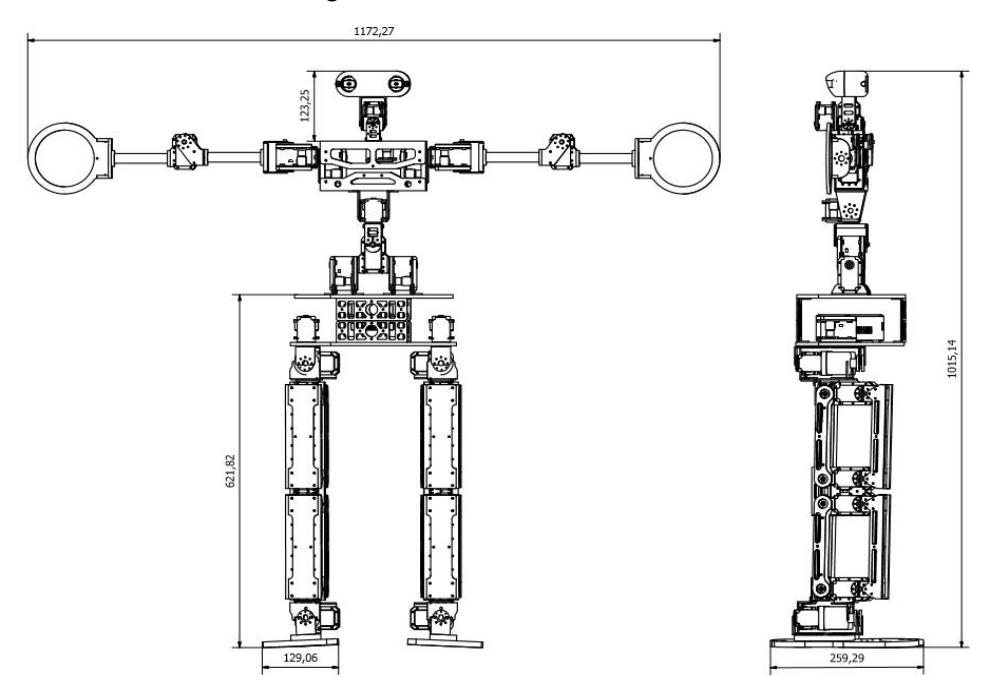
Robot Flow teen version of a humanoid robot designed with reference to the size of the RoboCup in the teen category size,The robot has a dimension, height 101,5 cm, width 25 cm, and weighs 8,25 kg with the total number of degrees of freedom total a 24 DOF.As for the design of two-dimensional front and side view of the robot shown in Figure.1
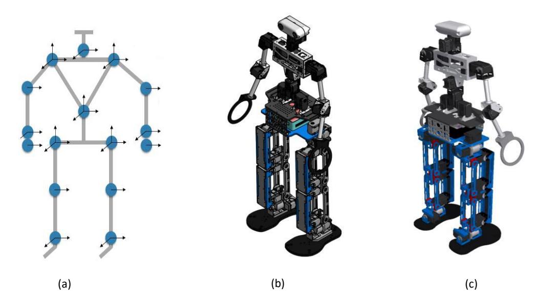
This robot is designed with the ability to move the joints (joint) as close as possible to human beings. This robot has a total degrees of freedom (degree of freedom) 24 pieces, as shown in Figure 2.a. distribution among other 6 DOF for each foot, 3 DOF for the waistline, 4 DOF for each hand in hand, as well as 3 DOF to the neck. As for the view isometry of these robots can be seen in figure 2. The thigh and calf of the robot is designed using a model of parallel links. This model was chosen in addition with the aim to remind the torque of the motor, as well as to reduce the existing load on the motor shaft. Some joint that require large rotary torque is also designed using parallel model uses two motors to drive the same shaft, among others, to move the joint at the ankle, hip and waist .
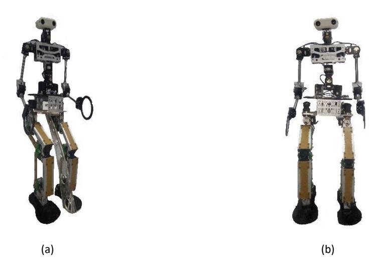
The design process of the robot is done by using a CAD program, and the process is then performed on manufacture using CNC machines. Materials for the robot chassis using a blend of aluminum material, Fiber plate FR4, and polyethylene (PE). The combination of these materials have been selected with the main objective to make the overall system as possible. To make the system remains solid, the design and construction made with regard to the structure of the material and the vector pressure of each section (part). Before the process of making parts, first performed stress analysis process on the system to ensure that there are no parts that deflection or deformation outside of a given tolerance. After the manufacturing process, each part is assembled according to the design created, made, and the results can be seen in Figure 3.
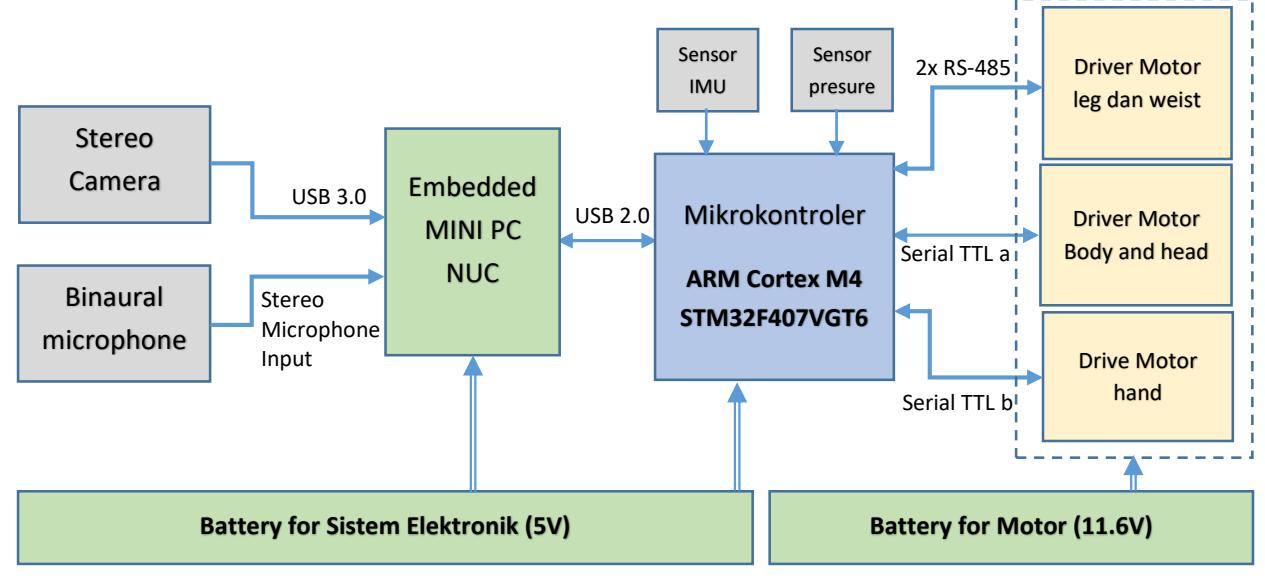
Robot flow Teen version using the mini PC as the primary controller and microcontroller with ARM architecture as a secondary controller. The main controller acts as a high-level controller with an emphasis on the ability of the robot to perform the reading of the environmental conditions, the navigation process of motion, as well as other intelegence system that will be added to the robot. While an additional controller to function as a low-level primitives controller for motion control of robots in performing process control at the component actuator (motor), internal sensor reading robot. The block diagram of the electronic system in general can be seen in Figure 4.
Stereo Vision System
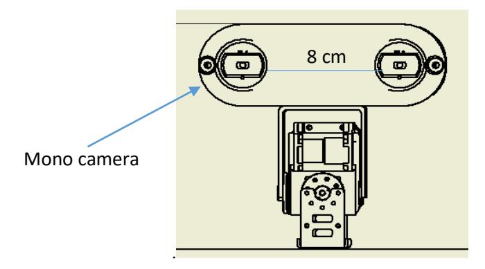
All of the objects in the field have a white base color on the ball, the entire goals, and the field lines, unless the field is a green color. The ball was identified as a moving object. This feature is used as the initial reference to find the ball. In addition to moving objects, the ball can be identified from the physical shape of a circle and depth object produced by stereo camera system. The distance between both of camera is 8 cm. Each camera is Microsoft Lifecam cinema high-quality 720p HD widescreen. For the actuators of head using a 3 dof in the neck with yaw, pitch and roll. For details in Figure 5.
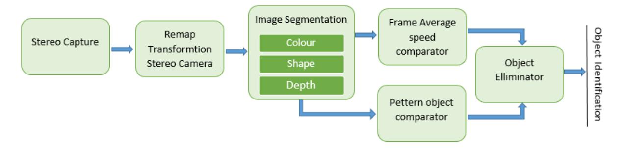
Object identification process is shown in Figure 6. Because it uses a camera stereo then there is a process of remap transformation stereo camera. That process for balance the position on the y-axis. the image segmentation, there are 3 information needed. The information is the color, shape, and depth. after segmented then find where the object is moving and not moving. That is for additional information to distinguish between the object ball and the two other objects that have the same color.
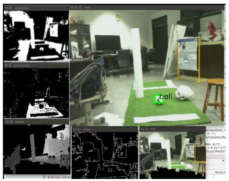
The vision system is able to identify objects such as balls Figure 7. Test results obtained success moving the ball identification. To recognize our ball using three segmentation, detecting color of the robot can distinguish where the location of the ball on the field, Detecting forms a rounded ball different from other forms and also use depth to determine the distance to objects that exist so will make it easier to identify a ball from the stereo camera.
Conclusion
The development has been done on the robot pose T-FLoW covers for robots, vision systems, and coordination. Pose higher around 3cm with an average walking speed 30 cm/sec. The results of identification by implementing the moving object detection a nd pattern moves on the vision system is able to identify the white ball within a maximum of 1.5m. With the results obtained at this time, the robots T-FLoW already have a basic ability to play football with the rules of the game in 2017. Further development is to improve the ability to take the ball without having to knock down the opponent robot. In addition, the development of artificial intelligence systems in the game as a control strategy for the coordinator and the other players. We hope that what has been achieved to meet the qualification requirements of RoboCup 2017
Statement of Willingness
Based on the results of the development we have done, we are hoping to qualify for RoboCup 2017. We hereby declare the ability when administered the opportunity to participate and will be very happy to be present to participate in the Robocup 2017 competition in Japan.
References
- https://www.robocuphumanoid.org, last accessed Desember 2016.
- Ill-Woo Park, Jung-Yup Kim, and Jun-Ho Oh, Online Biped Walking Pattern Generation for Humanoid Robot KHR-3(KAIST Humanoid Robot – 3: HUBO), in Proc. IEEE Int.Conf. on Robotics & Automation, pp. 398-403, 2006.
- Achmad Subhan KH, Ardiansyah A, Dimas Pristovani, EROS Team Description Paper for Humanoid Kidsize League for Robocup 2014
- Ahmad Subhan Khalilullah, Iwan Kurniato W, Dimas Pristovani, EROS Team Description Paper for Humanoid Kidsize League for Robocup 2015
- Robertson, P.; Angermann, M.;Krach B. (2009). "Simultaneous Localization and Mapping for Pedestrians using only Foot-Mounted Inertial Sensors". Ubicomp 2009. Orlando, Florida, USA: ACM. doi:10.1145/1620545.1620560.
- Jaulin, L. "Range-only SLAM with occupancy maps; A set-membership approach". IEEE Transactions on Robotics, (2011).