RO:BIT Team Description Paper for Humanoid TeenSize League of RoboCup 2019
Tae Gyeom Kim, Yeon Seo Lee, Chae Won Park, Ju Yeb Shin, Dong Hyeon Kim, Keon Hui Kim, Jun Hui Nam, Hyo Jae Park
Robot sports game team of Humanoid Robot School of Robotics, Kwangwoon University, Republic of Korea
Abstract This document describes hardware specifications, overall system of how robot works, image processing and dynamic control of humanoid. Our team strengthened competitiveness based on the experience of RoboCup 2018. We participate Humanoid TeenSize League of RoboCup 2019 with changed walking control of biped robot and image processing compared to last year's robot.
Introduction
Team RO:BIT is a professional robot game team of Kwangwoon University in Republic of Korea, established in November 2006. Humanoid team in RO:BIT researches autonomous humanoid and participates in several domestic and international competitions. We basically study in 4 fields: image processing(vision), robot design, control of biped walking, and control system circuit.
We participated RoboCup Humanoid League in 2017 and 2018, and we learned a lot about what we must improve through the competitions. We had improvements especially in image processing and walking control. We used deep learning for object detection instead of image processing which is fragile at lights and detecting objects far away. For stable walking, we are improving ZMP-based walk using load cell in aspect of walking control.
Overview of system
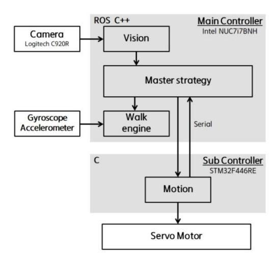
(refer to Fig. 1) Our robot system consists of a C920R Logitech USB camera, a NUC7i7 main controller and a sub controller. Main controller executes overall algorithms and object detection, walk engine and gyroscope acceleration data processing using ROS (Robot Operating System) on Linux. Sub controller, MCU based on STM32F446RE, controls motors (DOFs). Acceleration data from gyroscope is used to determine fall of robot and for balance control. Based on the data obtained from camera sensor, the main controller runs the whole robot driving algorithms and transfers the necessary motor motions to the sub controller, and the sub controller executes motion based on the data. The main controller and the sub controller are connected by serial communication.
3.1 Mechanical
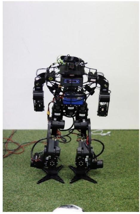
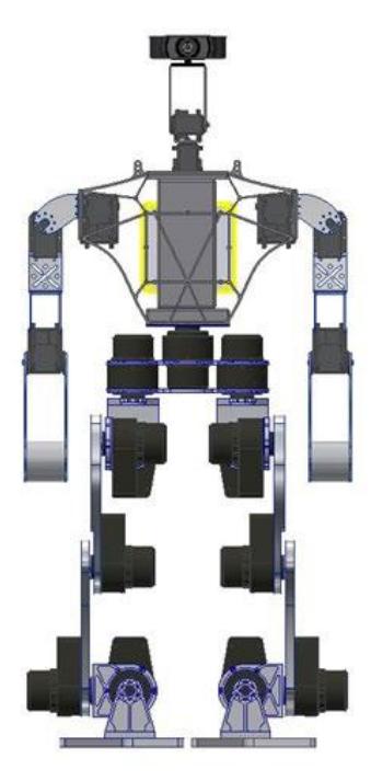
Robot consists of 21 DOFs, highs 860mm and weighs 12kg. For actuators, we used 13 ALM-Drives in legs, 2 MX-106s and 4 MX-64s in arms, and 2 MX-28s for pan-tilt. We used C920R Logitech USB web-cam for camera sensor. For battery, two 4Cell 2200mAH supply power to main and sub controller, and MX Dynamixels and 8Cell 8000mAH supplies power to ALM-Drives. 4 studs are attached at the corner of each foot so that our robot could walk stably in the field.
Table 1. robot specifications
| Items | Parameters |
|---|---|
| The name of the robot | RO:BIT |
| Height | 860mm |
| Weight | 12kg |
| Degrees of freedom | 21 |
| Walking speed | 25 cm/s |
| Type of camera | C920R Logitech |
| Computing unit | NUC7i7 |
3.2 Electronic
Our team uses self-designed sub controller based on STM32F446RE MCU and power board for actuators in legs. We control robot using firmware based on C-language, and this control system uses RS-485 for controlling ALM and MX actuators.
4.1 Object detection
The biggest problem with our team last year was significantly low accuracy of detecting objects. Last year, we detected ball using HSV color range filter and RANSAC algorithms. Since a ball consists of several colors, we added binarization image of different colors and applied RANSAC algorithms, and then trusted the data which is close to circle. However, this method was very sensitive to light and the surrounding environment, so it has low accuracy. Thus, we adopted deep learning for detecting a ball and other objects in the field.
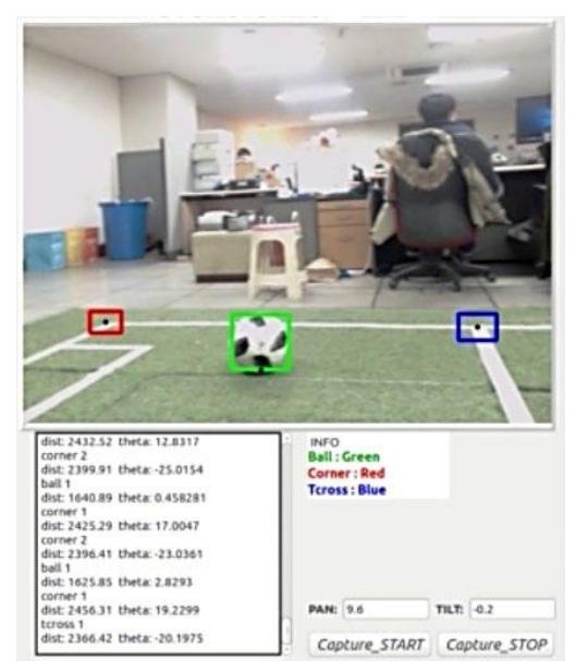
We used the YOLO [1] model. Since the main controller (NUC7i7) we are currently using does not have external graphics, robot detects objects using the YoloV3-tiny [2] model, which is the lightest model on Yolo. Learning is run on an external PC with external graphics and the learned data is imported to main controller and used for object detection. (refer to Fig. 3) Our robot now recognizes the corners of the field and the ball as a result of learning. The detected corner data will be used in our localization system.
4.2 Camera calibration
All objects in the field of play are detected using camera sensor. To recognize robot's state in the field distance and orientation of interested objects from robot are required. However, objects are projected on a 2D coordinate frame of camera in pixels. Geometric method is used to convert objects' position in 2D coordinate frame in pixels to 3D world coordinate frame. This method is executed using intrinsic camera parameters – focal length and principal point –, height of camera from the field and tilt of camera. Height and tilt of camera are given that we know robot's height and tilt is controlled by main-controller. Intrinsic parameters, camera matrix, are products of camera calibration [3]:
$$\mathbf{A} = \begin{bmatrix} f_x & 0 & c_x & 0 \ 0 & f_y & c_y & 0 \ 0 & 0 & 1 & 0 \end{bmatrix}$$
where $(f_x, f_y)$ is focal length, and $(c_x, c_y)$ is principal point. Afterward, 2D coordinate of object in pixels $(x, y)$ is converted to that of image plane $(u, v)$:
$$u = (x - c_x)/f_x$$
$$v = (y - c_y)/f_y$$
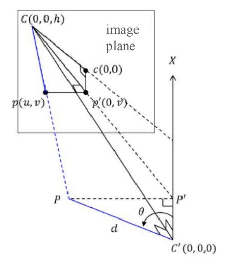
Using coordinate of image plane $(u, v)$, height $h$ and tilt of camera, distance and orientation of interested objects – ball, L-cross, T-cross and goalposts – from robot are calculated (refer to Fig. 4):
$$CC' = h$$
$$C'P' = CC' \times \tan\left(\frac{\pi}{2} + \theta_{tilt} - atan(v)\right)$$
$$CP' = \sqrt{(CC')^2 + (C'P')^2}$$
$$Cp' = \sqrt{1 + v^2}$$
$$PP' = u \times CP'/Cp'$$
$$d = \sqrt{(C'P')^2 + (PP')^2}$$
$$\theta = -atan2(PP', C'P')$$
where $(0, 0, h)$ is camera's position in 3D world coordinate frame, $(0, 0)$ the principal point in image plane, $P$ position of object in 3D world coordinate frame, and $d$ and $\theta$ are distance and orientation of object from robot. Last two products of equations are used in our localization system.
4.3 Localization
Our localization system uses information from GameController and feature points on field lines. Distance and orientation of feature points, L-crosses and T-crosses, from robot are calculated. Distance of this 2D information has accuracy in error range of 10 to 20cm, which we thought to be neglectable on 9m by 6m field. Then probabilities of robot's possible locations are calculated based on information of feature points and current state of robot from Game Controller. Location with highest probability is predicted as robot's current location on field.
Walking Control
We use both humanoid ankle axes as end effectors, create pattern which is a set of coordinates of end effectors over time, and then obtain the target angular position of each joints using inverse kinematics [4]. ZMP is not considered, and the pattern is geometrically drawn above each $x$, $y$, $z$ coordinate frame. Since patterns consist of several parameters, we can adjust the detailed shape of the trajectory as needed, which can control the walking parameters, such as how much pelvis will swing and how fast it will take to move the feet. These parameters are set manually by trials and errors to make walking the most stable. In this trial and error process, we use a manual tuning program that allows us to easily adjust parameters and test the response to the adjustment immediately.
5.1 Push recovery
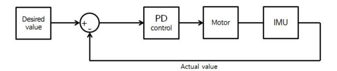
(refer to Fig. 5) To walk on artificial grass field, humanoids need to respond to the disturbance. For this, we have enhanced walking stability by using the 6-axis Inertial Measurement Unit (IMU) to recognize disturbance and then ensure that the robot responds to it properly by feedback control. The IMU is attached to the part of the body nearest to center of mass of the robot to estimate the angular position of the robot's torso and use this on feedback control. The PD controllers that make up the controller control the position of the pelvis, splice and ankle joints. If the estimated value of the angular position is outside a predefined threshold, it gives help to restore the value of the angular position to the normal range by using the movement of the pelvis, knees, and ankle joints in the opposite direction of the broken center of mass. This process helps keep center of mass in support polygon so that the robot is prevented from losing its balance and falling. The parameters of the controller and the threshold for angular position are also set manually through trial and error.
Within RoboCup 2018, our team felt the need for a more stable walk. Therefore, we are currently developing ZMP-based walking [5] using load cells, which we are expecting to be provided in RoboCup 2019 for a more stable walk.
Conclusion
This paper describes researches team RO:BIT developed and will be developing based on experience through RoboCup 2018, for RoboCup 2019. To solve problems encountered in RoboCup 2018, we had significant research development in image processing and walking control. We introduced deep learning to robot for detecting objects, and now we are in research at self-localization using particle filtering and expecting to demonstrate in RoboCup 2019. In respect to walking control, aside to feedback control, we are preparing more stable walking control using reference ZMP for RoboCup 2019. We put a lot of efforts for RoboCup 2019 and we will represent more developed robot than the one in RoboCup 2018 by newly introduced research technology.
References
- Joseph Redmon∗, Santosh Divvala, Ross Girshick, Ali Farhadi, "You Only Look Once: Unified, Real-Time Object Detection", IEEE Conference on Computer Vision and Pattern Recognition, 2016 IEEE Conference on. :779-788 Jun, 2016
- YOLO: Real-Time Object Detection. https://pjreddie.com/darknet/yolo/
- L. Deng, G. Lu, Y. Shao, M. Fei and H. Hu, "A Novel Camera Calibration Technique based on Differential Evolution Particle Swarm Optimization Algorithm", Neurocomputing, vol. 174, pp. 456-465, Jan 2016.
- Youngjin Choi, Doik Kim, Yonghwan Oh, and Bum-Jae You, "Posture/Walking Control of Humanoid Robot based on the Kinematic Resolution of COM Jacobian with Embedded Motion", IEEE Transactions on Robotics, vol. 23, No. 6, pp. 1285-1293, Dec 2007.
- Napoleon, Shigekhi NaKaura, and Mitsuji Sampei, "Balance Control Analysis of Humanoid Robot based on ZMP Feedback Control", IEEE International Conference on Robotics and Automation, vol. 3, pp. 2437-2442, Oct 2002.