Tech United Eindhoven Team Description 2009
W.H.T.M. Aangenent, J.J.T.H. de Best, B.H.M. Bukkems, F.M.W. Kanters, K.J. Meessen, J.J.P.A Willems, R.J.E. Merry, M.J.G. v.d. Molengraft
Control Systems Technology Group, Eindhoven University of Technology, Den Dolech 2, P.O. Box 513, 5600 MB Eindhoven, The Netherlands
Abstract This paper describes the research improvements in the mechanical, electrical and software design of the robots of team Tech United Eindhoven. The main improvements are the world model, the new strategy framework, the front camera, the improved active ball handling mechanism and the new kicker design.
1 Introduction
Tech United Eindhoven is the Middle Size RoboCup team of the Eindhoven University of Technology, founded in 2005 and participating in the Middle Size league since 2006. Team Tech United Eindhoven mainly consists of PhD, MSc, BSc students and staff members from different departments within the Eindhoven University of Technology.
This team description paper is based on the status of Tech United Eindhoven in January 2009 as part of the qualification package for the RoboCup World Championships 2009 in Graz, Austria. This paper describes the most significant improvements and developments of the previous year.
First, a brief introduction of the Tech United Eindhoven robot platform is presented. Next, the main improvements compared to [8] are described, namely: (i) the world model, (ii) the integrated dynamic strategy platform, (iii) the high speed front camera, and (iv) the improved mechatronic aids.
2 Robot Platform
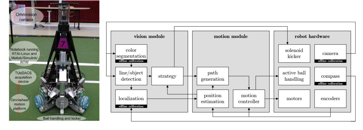
The Tech United Eindhoven robots are called TURTLEs (Tech United RoboCup Team: Limited Edition). A picture of the fourth generation robots is shown in Fig. 1. The stability of the platform has been improved by placing parts at a lower position in the robot, which lowers the center of gravity and enables a higher acceleration. For data acquisition and motion control, the robot is equipped with EtherCAT devices [7, 9], which are connected to the onboard host computer via ethernet. Power is supplied by two Makita 24 V, 3.3 Ah batteries. The Maxon motors are driven by Elmec Violin 25/60 amplifiers. Furthermore, a capacitor of 350 V with a capacity of 4.7 mF is installed for the solenoid shooting mechanism. Each robot is equipped with a mini-PC running a preemptive Linux kernel. The robot software is automatically generated from Matlab/Simulink models via the RTW toolbox. In this way, a modular software framework is obtained, see Fig 2.
3 World model
The latest software version provides a TechUnited-tailored version of the CAMBADA communication layer [4] and, on each TURTLE, a world model containing the TURTLE's local state and the communicated states from other TURTLEs. Here, the state typically contains the position and velocity of TURTLEs, opponents and the ball.
Given a number of moving objects in the soccer field, the main questions are: 1) how to associate measurements with objects in the field and 2) how to track the object positions and velocities in real-time. A well-known problem of existing data-association algorithms is the practically bad computational scalability to real-life situations with a large, but a priori unknown, number of objects and a large number of measurements. Such methods suffer from combinatorial explosion as each new measurement increases the number of possible associations with a more than exponential growth. We developed a combined data-association/tracking method that handles a case with 20 measurements per time step and 10 moving objects within a few milliseconds on modern PC hardware.
This work has been inspired by [6]. We adopt the idea of a tree of data-association hypotheses. [6] considers static objects only, whereas in the soccer application the environment is highly dynamic. In our approach, each possible object will be characterized by a constant Kalman filter. The basic model in this filter assumes a constant velocity in the field, which is adapted by the filters innovation signal. To prevent the tree of hypotheses from exploding, we apply a rigorous form of pruning. After the tree has been extended with the possible associations for a new measurement, all branches with small probability are removed from the tree. The probability of each branch in the tree is filtered in a Bayesian way using both model and measurements. Only the most likely branches of the tree are allowed to grow further. The branch with the highest probability reflects the current number of recognized objects and their corresponding states.
The above method, used as input to the world model, appears to be both fast and robust in the presence of noisy measurements. Although the world models of all TURTLEs are not guaranteed to be consistent, the differences appear to be small in practice, which helps to prevent shattering in the decision making of the strategy.
4 Strategy
The game play that has formerly been used by Tech United was based on individual play and almost static roles. This means that each robot had its own assigned role, which is performed during a game. The possible roles are: attacker, assistant attacker, defender, assistant defender and goalkeeper. This way of playing has some serious drawbacks. First of all, there is no real team play, i.e., there is a lack of explicit cooperation. Ideally, the robots would make a joint decision accounting for the momentary state of the environment and for the assigned roles. Secondly, there is no learning involved, where it would be advantageous to alter behavior based on the success or failure of certain actions.
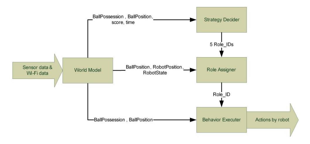
To tackle both above mentioned drawbacks, we are currently developing a new strategy in which team play is the central topic. This strategy basically consists of four items: (i) the World Model, (ii) the Strategy Decider, (iii) the Role Assigner, and (iv) the Behavior Assigner, as schematically represented in Fig. 3: The World Model was already discussed in Section 3. The Strategy Decider block has as inputs, amongst others, the score and the remaining time. Based on this information this block selects a fitting strategy that is to be applied, i.e. a combination of a formation (e.g. 1 keeper, 2 defenders, 2 attackers) and a tactic (e.g. center attack, tight defense). The Strategy Decider has the following functionality: (1) load formations and tactics before the game starts; (2) dynamically choose new formations and tactics during the game, based on the environment information; (3) send a list of 5 unique role identifiers (5 Role IDs) to the Role Assigner, based on the chosen formation and tactic.
The Role Assigner is the component in charge of determining the applicability of the roles with respect to the robots and assigning the most suitable role to each robot. In other words, the role assigner determines robot a set of suitable roles for each robot and a rank for each role as a measure of its applicability. On the basis of these ranks, the Role Assigner assigns to each robot the most suitable role while avoiding conflicts with the assignment of this role to another robot. The ranking is based on information about the mechanical state of the robot, the positions of the robot and its team members, and the position of the ball.
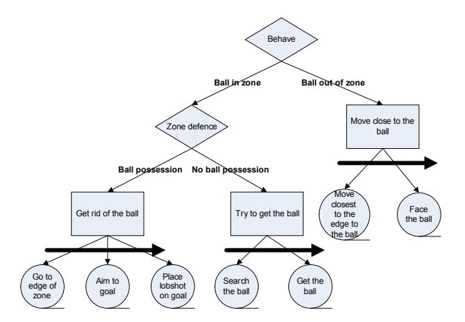
Finally, the Behavior Executer block executes the behavior that belongs to the assigned role (Role ID). The behavior has to make decisions that are based on the environment at that time. For this purpose, it requires information from the World Model. The assigned role is constructed based on a behavior tree, which consists of the following three types of nodes: Selector, Sequence, and Action, see Fig. 4. The reason that we choose for a behavior tree over for instance a finite state machine is that behavior trees support a clear visual interpretation. The design uses weights for selecting a strategy and assigning the roles. These weights are a priori defined and during the match these weights cannot be changed. In the future, learning will be added to adjust the weights during a match such that a robot will make different decisions as the match develops.
5 High speed front camera
In a soccer game timing and accuracy are extremely important. To control a ball that is coming from a different player, e.g. for ball passing one has to predict very accurately at what time the ball is at a certain position to correctly position the players foot to control the ball. Humans do this by continuously looking at the ball and predicting its trajectory. Real-life soccer shows that this is not trivial, since very few soccer players are capable of controlling every ball that is coming in their direction. For a robot to perform the task of controlling a ball that is coming towards the robot, an accurate ball trajectory prediction both in space and time starts with a good vision system. With balls reaching speeds of 10 meters per second an omnivision camera at 25 framesper-second (fps) is not suitable for this task. Also, the omnivision system is not able to observe ball movement above 80 cm. Present day matches often show lob shots at heights above this 80 cm. Therefore, a high speed (200 fps) front camera system [5] is added to accurately locate balls coming towards the robot.
5.1 Smart camera
Video data at a resolution of 640x480 pixels and at a rate of 200 fps is very demanding both in terms of I/O and in terms of processing. The Vision Components VC4458 [5] is a camera with on-board processing power, which is chosen because of its high computing power and high speed at full resolution (up to 242 fps @ 640x480 pixels). All processing and analysis of the video images is done on the smart camera and only the ball position and velocity will be communicated to the main mini-PC.
5.2 Lighting correction
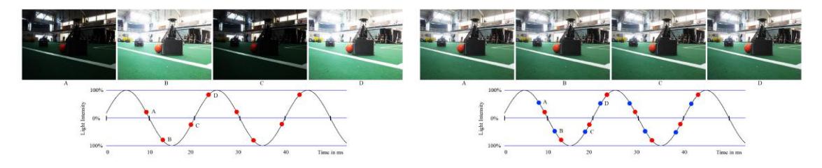
With high speed video applications, lighting is very important. The objects that have to be located should be sufficiently lit, but also constantly lit over time. At 200 fps, a normal light source working at 50/60 Hz will not result in constant lighting, see Fig 5. In many high speed video applications, LED lights or DC light sources are used instead of AC powered sources. However, in RoboCup the lighting is fixed and in many cases driven by AC power. The difference in lighting between frames should be corrected. The first countermeasure used is triggering on the correct phase of the AC powered light source. Detection of the phase and frequency is done by running the camera at a high speed (not a multiple of 50 or 60 Hz) for several seconds on a fixed object. In this sequence the mean intensity of each frame can be calculated and fitted to a sine function to obtain frequency and phase of the illumination. Once the phase of the light source and its frequency are known, one can trigger the image acquisition of the sensor to the correct phase, as shown in Fig. 6.
5.3 High speed ball detection
To detect a ball in an image at 200 fps, the algorithms should be fast and simple. Since the camera is a grey-scale camera, color filtering on the lens can help selecting good candidates for the ball (of course this applies only for balls with a fixed, known color). The first step in the ball detection algorithm is adaptive thresholding, followed by region labeling [10]. Next, shape descriptors, such as roundness and size, are calculated for every region. With these descriptors, the candidate regions can be ordered from 'very likely a ball object' to 'unlikely a ball object'. The final step of the ball detection algorithm is selecting the most likely ball object and calculating the confidence measure for that region being a ball object. Once the most likely region is selected the position and size of the object in image coordinates can be easily extracted. These are then converted to world coordinates (using a fixed, known size of the ball and a fixed, known camera position, the z position can be estimated) and send from the camera to the main control system of the robot. In the near future, a prediction model will be combined with the data to obtain a more robust estimate of the ball position and the ball speed.
5.4 Communication
The VC4458 camera has several methods for communication between the camera and the host mini-PC, such as an ethernet port and a serial port. All communication on the robot between host mini-PC and I/O is done via a Beckhoff EtherCAT module [2], controlled by the host mini-PC. For transparency on the software side, it is chosen to develop a dedicated serial EtherCAT slave, connected to the camera via the serial port. In this way, the camera acts as a smart I/O module that measures the ball position and speed in 3D world coordinates.
6 Innovative mechatronic aids
In this section the innovative mechatronic aids are described, namely: (i) the active ball handling mechanism and (ii) the kicking mechanism.
6.1 Active ball handling mechanism
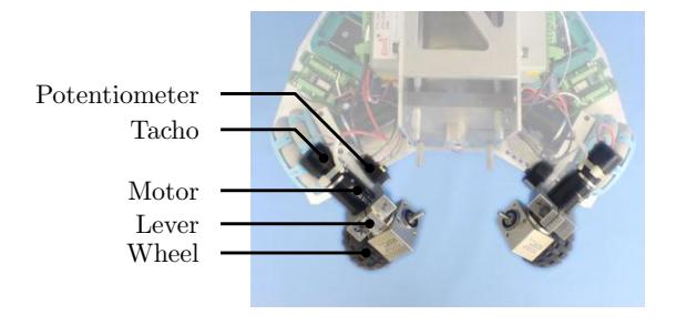
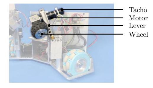
The 2008 version of the ball handling mechanism of the TURTLE platform is shown in Fig. 7 and Fig. 8 [3].
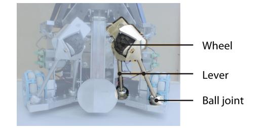
The main part of the ball handling mechanism consists of two levers. At the end of each lever a wheel is mounted. These wheels are actuated by DC motors and the velocities of these wheels are measured using tachometers. The levers can rotate around fixed points on the robot and the angles of the levers can be measured.
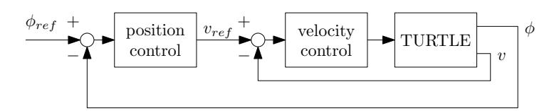
The control architecture that is used is a hierarchical one, see Fig. 9. On the low level, it consist of two velocity control loops to track a motor velocity reference $v_{ref}$ and to account for disturbances acting on motor level. On the high level, the control architecture contains two position control loops, one for each lever, to control the angles of the two levers $\phi$ . All controllers are SISO based controllers. This can be done only if the levers are placed under an angle of 90° with respect to each other. In such a way, we effectively create a decoupled system valid within the frequency range of interest, which is below 10 Hz. Above this frequency, the system is not perfectly decoupled and SISO control techniques cannot be applied.
A preferred distance from the ball to the front of the robot can be defined, which results in preferred angles $\phi_{ref}$ of the two levers. If the levers are bending forward a position error is introduced which is controlled towards zero by adjusting the velocities of the wheels. If the levers are bending backward the wheels will spin in the opposite direction such that the ball is slightly pushed away from the robot. Without a ball, the wheels keep spinning. Since the robot also has to move, additional effort is necessary in order to maintain the levers at the preferred angle during these movements. This issue can be tackled using feedforward. The input for the feedforward is the velocity (translational as well as rotational) of the robot itself, which can be derived from the encoders. The active ball handling mechanism is superior to the commonly used passive ones for multiple reasons:
- It introduces the opportunity to drive backwards while still possessing the ball.
- The position of the ball with respect to the robot can be adjusted. This property can be exploited for example to produce special kicks, e.g. under an angle.
- Dribbling with the ball becomes much simpler since it is not necessary to constantly rotate around the vertical axis of the ball.
During all moves, the ball will keep rolling in a natural direction. Furthermore, during a game the ball does not enter the convex hull of a robot by more than a third of its diameter as is stated in the rules and regulations [1].
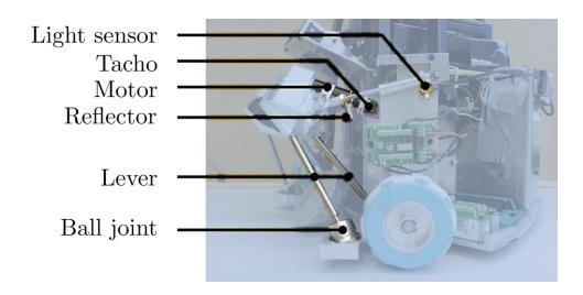
One can imagine that during game play collisions with the other robots are unavoidable. During these collisions, high forces can be exerted on the ball handling levers, probably causing undesirable plastic deformations or even total fracture. Therefore, the above described mechanism has been completely redesigned to be more robust against such collisions. The new design is shown in Fig. 10 and Fig. 11. As can be seen from these figures, the wheels are partially covered to prevent cuts by sharp edges of other robots. Furthermore, the lever now consist of two rods which are mounted on the base plate of the robot with rubber-cushioned ball joints. During collisions the rubber is compressed such that an elastic deformation region is created to absorb the energy of the impact. To measure the position of the levers, a light sensor is used in combination with a reflector, which is invariant to environmental light, see Fig. 10. The control principle is the same as in the previous design.
6.2 Kicking mechanism
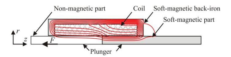
The shooting device of the robot is an electromechanical solenoid consisting of a cylindrical coil and a plunger. The plunger has a soft-magnetic part and a non-magnetic part. By applying a current trough the coil, the reluctance of the magnetic flux is minimized by putting the soft-magnetic part of the plunger inside the cylindrical coil, as can be seen in Fig. 12.
The advantages of using this type of electromechanical actuator is the relatively simple structure with one coil and a soft magnetic mover in contrast with, more efficient, permanent magnet actuators.
To provide power for the solenoid, a 350 V, 4.7 mF capacitor is used as a buffer that can be charged from the central power supply of the robot. To control the amount of current through the coil, an IGBT is used as a switch between the capacitor and the solenoid.
Starting from last year's design [8], a number of improvements have been made. A smaller solenoid has been designed that can still produce a peak acceleration of the plunger of 700 ms$^{-2}$ . This results in a final speed of the plunger, i.e. the speed of the plunger when the ball leaves the kicking device, of 9 ms$^{-1}$ . This speed results in high eddy currents in the plunger causing additional damping. To minimize these eddy currents, four narrow slits are milled in the axial direction of the plunger, resulting in an improved performance.
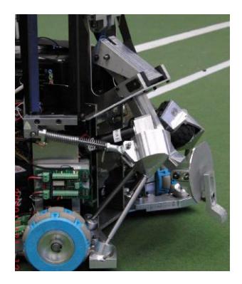
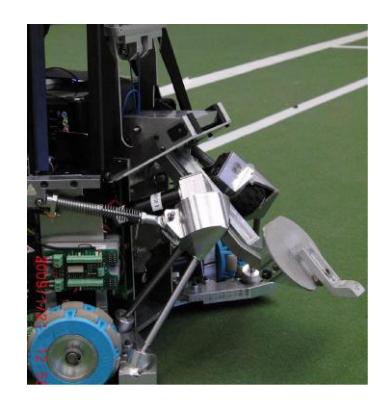
By applying pulse width modulation (PWM) to the gate of the IGBT, the amount of current through the coil can be regulated resulting in a controllable force, and hence a controllable final speed of the leg. Additionally, the angle of the foot of the ball shooter can be adjusted to be able to give the ball a certain starting angle with respect to the ground, see Fig. 13 and Fig. 14. This results in a fully controllable shot, which gives the possibility to pass the ball to another robot, and to adjust the height of a shot according to distance to the goal.
The duty ratio of the PWM is based on a lookup table generated in a calibration experiment. Additionally, the speed of the kicking leg is actively controlled, which is done by measuring the rotary velocity of the leg with an incremental encoded and feeding it back tot the PWM duty cycle in order tot minimize the effects of disturbances such as friction. The front camera of the robot provides additional feedback of a shot as it can see the traject of the ball and the landing position. This information will be used to continuously adjust the control parameters.
As one shot takes approximately 20 ms, the leg speed controller requires a high sampling frequency. Therefore, this controller is implemented on an ETRAX 100LX microprocessor [11] running a real-time Linux distribution. For the I/O of this microprocessor, a second EtherCAT stack is used. This stack contains an encoder module for the plunger position and a PWM module to switch the IGBT.
7 Conclusions
Compared to the situation described in the previous team description paper, Tech United Eindhoven has advanced significantly. The implementation of the world model in combination with the newly developed strategy framework greatly improves the team tactics. The use of a high speed front camera results in fast ball tracking. The improved ball handling design is more robust and the improved kicking mechanism results in a better reproducible shot. All new developments together should yield an improved game performance, at least matching and hopefully improving last years' results in the RoboCup Middle Size league.
References
- MSL Technical Comittee 1997-2009, Middle Size Robot League Rules and Regulations for 2009, Version - 13.1 20081212, (2008)
- Beckhoff, Main catalog, http://www.beckhoff.de/download/document/catalog/main catalog/english/ main catalog 2009.pdf (2009).
- J. de Best, R. van de Molengraft, An active ball handling mechanism for RoboCup, in: International Conference on Control, Automation, Robotics and Vision, Hanoi, Vietnam, 2008.
- J. Azevedo et al., CAMBADA 2008: Team description paper, RoboCcup, 2008
- Vision Components GmbH, Datasheet Vision Components Smart Camera VC4458, http://www.vision-components.com/files/VC44XX/E/VC4458 E.pdf (2008).
- H. Sidenbladh and J. Schubert, Sequential clustering with particel filters estimating the numbers of clusters from data, in: Proc. of 8th Int. Conf. Information Fusion, Philadelphia, US, 2005.
- D. Jansen, H. Buttner, Real-time ethernet the ethercat solution, Computing & Control Engineering Journal 15 (1) (Feb.-March 2004) 16–21.
- J. Lunenburg, G. v.d. Ven, Tech United Team Description, http://www.techunited.nl (2008).
- S. Potra, G. Sebestyen, Ethercat protocol implementation issues on an embedded linux platform, Automation, Quality and Testing, Robotics, 2006 IEEE International Conference on 1 (May 2006) 420–425.
- H. Samet, M. Tamminen, Efficient component labeling of images of arbitrary dimension represented by linear bintrees, IEEE Transactions on Pattern Analysis and Machine Intelligence 10 (4) (1998) 579–586.
- Acme Systems srl, Datasheet fox board, http://foxlx.acmesystems.it/foxlx acmesystems it/00004/ FoxDescription en.pdf (2006).