WinKIT 2009 Team Description Paper
Yuichi Komoriya, Ryoma Hashimoto, Keisuke Miyoshi, Yuya Ogawa, Daisuke Sakakibara, Jun Sawada, Kazuya Tahara, Hiroaki Fukushima, Kazuki Mitani, Ryo Yamakage, Yasuki Asano, Kosei Demura
Factory for Dreams and Ideas. Kanazawa Institute of Technology 7-1 Ohgigaoka, Nonoichi, Ishikawa 921-8501, Japan; Department of Robotics, Kanazawa Institute of Technology 7-1 Ohgigaoka, Nonoichi, Ishikawa 921-8501, Japan
Abstract This paper describes our research interests and technical information of the WinKIT team for RoboCup 2009. Our robots have been developing to have a capability of pass-based tactics since 2002. Through the activity, we have improved accuracy of self-localization, a team formation, and an obstacle avoidance. In the 2006 championship, however, WinKIT defeated in the first round robin, and we noticed that our robot system was not the state of arts in the RoboCup 2006. From the year, we have been developing a new robot system to catch up with top teams. As a result, the WinKIT team completed the seventh generation robot to participate in RoboCup 2009. The characteristic of the new robot is a stronger kicking device, improved motion performance by a four- wheel drive system, collision avoidance with a fuzzy potential method, and a new vision system which has a capability of color constancy.
Introduction
The WinKIT team at the Kanazawa Institute of Technology (KIT) won second place at the RoboCup 2002, 2003, and 2004 World Championship. The WinKIT team won the eight bests in the RoboCup 2005 World Championship. Core member of the WinKIT team are all undergraduate students. The team, however, left many good results at the championships.
The secret of this splendid feat is in our educational system, Yumekobo, the factory for dreams and ideas [1]. In 1993, KIT established Yumekobo to encourage students to create things and make character building. The most important activity of Yumekobo is to support student projects called Yumekobo Projects whose purpose is to improve technology and teamwork. During actives in Yumekobo projects, students experience the process of creating things, i.e., planning, investigating, designing, manufacturing, analyzing, and evaluating. In addition, they learn how to organize and manage a project. The WinKIT team is one of Yumekobo's student projects as described above. Currently, student teams in Yumekobo have been obtaining remarkable results in various domestic and world championships. Yumekobo was introduced as one of new educational ideas in the World in Newsweek International [2].
Hardware
(continued in subsections)
2.1 Specification
Fig.1 shows our seventh generation robot and Table.1 shows the specifications of the robot. The robot is equipped with a four-wheel drive system, an omnidirectional and a directive camera, a solenoid kicking device, and a ball handling device. The change with last year is a platform, from a three-wheel drive system to a four-wheel drive system, to improve motion performance and fault tolerance.
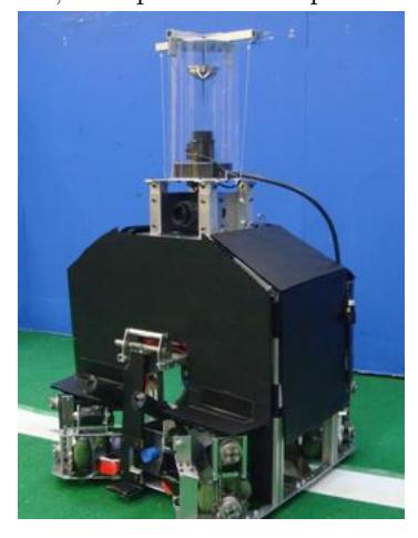
Table 1. Specifications
| sixth generation robot | seventh generation robot | |
|---|---|---|
| Dimension(L × W × H) | 460mm × 498mm × 685mm | 440mm × 492mm × 710mm |
| Weight | 18 kg | 19 kg |
| Moving System | Omni-directional drive | Omni-directional drive |
| 3 omniwheels | 4 omniwheels | |
| Maximum speed | 3.0 m/s | 3.5 m/s |
| Computer System | Lenovo ThinkPad X60 | |
| Processor | Intel Core2 Duo processor T2300 | |
| Camera | PointGrey Research Inc. DragonFly2 | |
| Omni Mirror | Seiwa-Pro Panorama Eye |
2.2 Hardware System
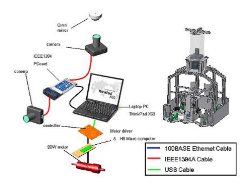
Fig.2 shows an overview of our robot system. A laptop computer, Lenovo Thinkpad X60, is used to control the robots, and its operation system is the Linux. The robot is sharing information by a wireless LAN, and control motors by a selfmade motor driver via USB interface.
2.3 Kicking Device
Fig.3 shows a kicking device under development. We have been developing a solenoid based kicking device. It has a capability of shooting a loop shoot and a grounder shoot. To kick a ground shoot, it uses only the solenoid, and to kick a grounder shoot, it uses a kick plate with the principle of leverage and a latching solenoid. Moreover, it can control kick force. Sixth generation robot can kick a soccer ball 8m. This year, in order to kick a more powerful shoot, changing the solenoid core from S45C iron to 78-Permalloy which has a high magnetic permeability, and the design of the kicking mechanism. From these changes, compared to last year, the robot can kick a more powerful shoot. The new kicking device can introduce new soccer tactics to us.

2.4 Handling Device
A ball handling device was introduced from the sixth generation robot. The device, however, reduces flying distance of a ball because that a part of it blocks a trajectory of a loop shoot. Thus, we are redesigning a new device to prevent interference between a ball and the device.
2.5 Motor Driver and Motor Controller
A motor controller which uses a H8/2212 processor of Renesas Technology via USB interface is developed. The motor controller is measuring heat and the current of the motor to fault tolerance.
Software
(continued in subsections)
3.1 Robot Action
Our robot can get the precise action that accepted a situation of a match. The robot uses information of a referee box, information of other robots of our team, information of one's camera and judge the situation of the match precisely. It selects a precise action by applying that information to an evaluation function selecting a team formation, and an evaluation function selecting an action.
3.2 Obstacle Avoidance
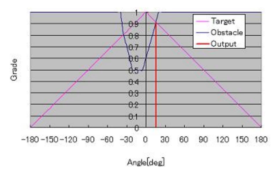
Because a vision system changed in 2007, we changed a method of an obstacle avoidance greatly. The method, the fuzzy potential, functions by resembled potential method. Fig.4 shows relations between a grade of a target angle and a grade of an obstacle distance and an output angle. The grade of the target angle is decided by the difference between the output angle and the target angle that is received from the action layer. The figure has the obstacle within the range from -40°to 25°. Especially, the point that approaches most is -15°. The angle where the grade of the target angle is corresponding to the grade of the obstacle distance becomes the candidate of the output angles, and it outputs angle finally at the angle where the grade is the highest in those. This method is very simple, however it shows better performance compared with the past method.
3.3 3D Physics Simulator
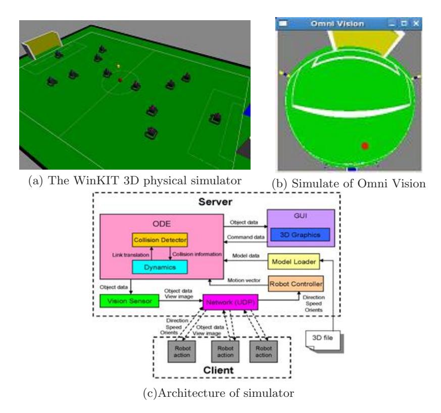
Fig.5(a) shows the WinKIT 3D dynamic physics simulator, which has been developing since 2004. The purpose is evaluation of a software and a test of a cooperative play, and tactics. The simulator uses an open source physics engine, Open Dynamics Engine, which is a high performance library for simulating rigid body dynamics. In addition, it is uses a simple 3D graphics library based on the OpenGL graphic library. A virtual robot on the simulator equips with an omni directional system, and a virtual robot made in the image of a real machine.
Fig.5(c) shows the architecture of the simulator. The system of the simulator is based on a client-server architecture. The process of a virtual robot runs independently. It is able to test for many robots by connecting clients, which become virtual robots, to a server. This server sends the information of sensors and position on each robot to the client. A client decides the action based on the information, and sends the action information to a server. Information exchange between robots is realized through a server. As a result, it is possible to evaluate cooperative play. The simulator is compatible with the programming environment of a real robot. It has the same function to acquire the sensor information of a real machine. It is possible to run the same source code, which was developed in the simulator, on a real machine. This simulator cannot completely simulate our new vision system. Therefore we have developing a vision module to simulate our new vision system. Fig.5(b) shows a camera image of the simulator, although it is a development stage.
3.4 Goal Detection
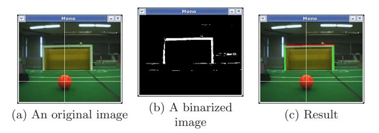
With revision of the rule, we are trying to detect a goal without using information of the color by using OpenCV and a camera. First, robot creates an image which displayed only the color of the goal frame from the acquired image. Secondly, it detects the length of the lines which is perpendicular to the field of the image. With this, the lines which can become a goalpost can be detected. Thirdly, it examines whether or not the longitudinal-direction is the color of the frame of the goal from the upper end of the detected lines. If different, it stops there. At the same time, it records how many pixels it was possible to investigate. With function, the length of the lines which can become a cross bar can be detected. As for the condition of the crosswise direction in this case, there is not level need in the field. Finally, it detects one thing as the goal using the location relationship of the line which can become a goalpost and the line which can become a cross bar as shown in Fig.6.
Research Topics
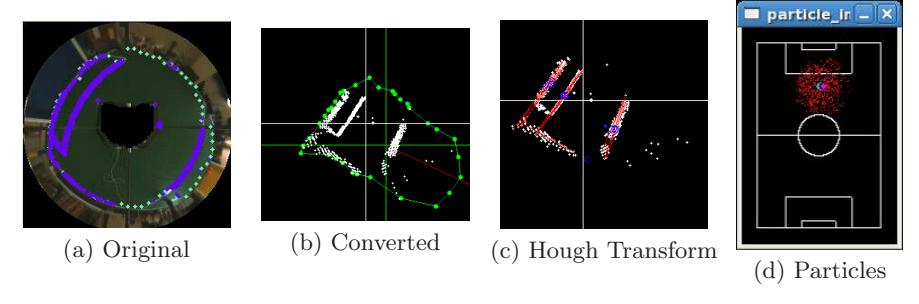
A self-localization is the most important technology for RoboCup. We derived a self-localization from the landmarks such as a goal or a pole, since a team start. However, with revision of the rule, the number of landmarks such as goal and pole that a robot was able to detect has decreased. Therefore, it became difficult to demand correct self-localization by the conventional method. Therefore we devised method to demand a self-localization from the domain of the field and white line, without using landmarks.
We explain a flow of rough processing. Firstly, robots find a rough selflocalization by the domain of the coat from the image of an omni vision. Secondly, robots do Hough transformation of the white line which robots detected. And robots derive the degree of leaning of the coat from a result of the Hough transformation. And robots make the template of the field based on the result for template-matching. Thirdly, robots make template matching with the information of the template and the white line, and it makes vague localization information a reliable thing [4]. Finally, it fuses by the Monte Carlo method by information of localization and dead reckoning. This method has better precision than the conventional method [5][6].
Conclusion
We did a lot of new trials and huge progress since 2006, such as a stereo vision system, a Monte Carlo based self-localization, an obstacle avoidance and a kicking device. As a road map of the RoboCup, the color of a robot and a ball will be abolished. We think that the stereo vision system has an advantage for obstacle avoidance and precise localization. When we introduced it experimentally, distance was calculated very precisely up to 3m ahead. But, it took image processing time enormously. To shorten processing time is our future work.
The outdoor match will be performed in near future. We have been developing a vision system which is robust under a natural light. This year, for the first step, we have developed the new vision system which has a capability of color constancy based on relative color values compared with a white reference part of the robot.
References
- K.Demura, M.Tani, Y.Hattori, "The Yumekobo Project Education at Kanazawa Institute of Technology (in Japanese)," Journal of Society for Engineering Education, pp. 128–135, 2006.
- B.Kantrowitz, "Learning the Hard Way," Newsweek International, 15, p. 50, 2003.
- Y.Nakagawa and K.Demura, "Collision Estimation from Information of an Omnidirectional Camera (in Japanese)," Proceedings of 2006 JSME Conference on Robotics and Mechatronics (ROBOMEC'06), 2P1-B04, 2006.
- Y.Nakagawa and K.Demura, "Self-Localization using White Line with Omnidirectional Camera (in Japanese)," Proceedings of the 25th Annual Conference of the Robotics Society of Japan, 2N14, 2007.
- K.Demura and Y.Nakagawa: "Monte Carlo Localization using White Lines of Omnidirectional Images (in Japanese)," Proceedings of the 26th Annual Conference of the Robotics Society of Japan, 1L2-01, 2008.
- K.Demura and Y.Nakagawa, "A Monte Carlo Localization based on Template Matching using an Omni-directional Camera (in Japanese)," Journal of the Robotics Society of Japan, (to appear).