MRL Middle Size Team: RoboCup 2011 Team Description Paper
M.Gholipour, S.Ebrahimijam, H.Rasam Fard, M.Montazeri, A.Mohseni Zanjaninejad, S.Moein, B.Eskandariun, M.Mahmoodi, H.Ziarati, A.Zarineh, M.Ghafouri Tabrizi, A. Aryandust
Mechatronics Research Laboratory, Islamic Azad University of Qazvin - IRAN
Abstract This paper concisely describes the very main and new features of our soccer playing robots along with the improvements made since the previous years. Our major concerns for this year's competitions have been developing a complete passing scenario, equipping robots with new kicker tools, also developing new features in vision and software which are cooperative team behavior synchronization and emotional intelligence.
1 Introduction
The MRL middle size team has started its work at Mechatronic Research Laboratory of Azad University of Qazvin since Aug 2003. This team aims at establishing an intelligent control method for autonomous multirobot systems in dynamic uncertain environment. MRL has begun the research and work in MSL since 2004. Our first official participation was during RoboCup 2005 competitions in Osaka and then Robocup 2006 in Bremen. We optimized hardware, control and software system for Robocup 2008 and designed robust system for Robocup 2009 in Graz, as a result we find ourselves between four top teams. In Robocup Singapore 2010 competitions we got the first place of technical challenge and again forth place of league competitions. We believe that, the Intelligent, cooperative and adaptive behavior of the robots is very important factor for a team success. With this regard our research is continuously focused on: reliability, sensor fusion, dealing with uncertainty of environment for the robots, world modeling and dealing with missing information. In the following sections we briefly explain current status and new achievements of our team.
2 Hardware and mechanical features
This year we designed a new flexible and powerful 4-wheel omnidirectional robot which is shown in figure 1. The design major features are smaller dimensions, less shaking. Motors are MAXON EC 200watt brushless motors for increasing the speed. The four-wheel drive robot can move at any direction and at any moment. The new omnidirectional wheels and platform shows more efficiency despite simplicity. Also a modified version of our last year kicker was redesigned a new multi power kicker for efficient cheap kicks and pass.
Main processor is Lenovo X200 notebook PC and electronic equipments are developed ARM Cortex M3® -LPC1768 microcontrollers with high speed CAN-bus, each robot was equipped with two UI-2210-C cameras with USB communication protocol one in front and one on the top. Other electronic devices like Li-Polymer Batteries, Infra Sensors are the same as last year [1].
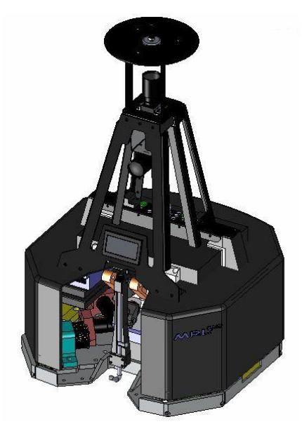
Hardware specification of the robot
| Items | Description |
|---|---|
| Platform | 4 wheel |
| Omnidirectional | |
| Max speed | 3.5 m/s |
| Max acceleration | 4 m/s2 |
| Kicker | Electromagnetic |
| Weight | 40 Kg |
| Laptop | Lenovo X200 |
| Camera | uEye UI-2210-C |
| Image processing | Omni directional mirror |
| Other sensor | IMU and IR |
| Controller | Neural Network PID |
| Spin back | Active 60watt 24V DC motor |
2.1 Robot control architecture
Distributed systems are suitable for complicated system because the tasks are distributed between every part [2], so each part is responsible for its own duties. By using such method the control system becomes more flexible because the error detection is easier and fast to recover. Successful distributed sensing and control require data to flow effectively between sensors, processors and actuators on single robots [3], in groups and across the Networks. With this regard the control systems are partitioned into low level and high level control systems.
Low level control: the policy that controls low level I/O peripherals of each function distributed in a robot system such as motor control and robot navigator system.
High level control: the policy that controls whole system, such as localization system or decision making control [4].
2.2 Low level control
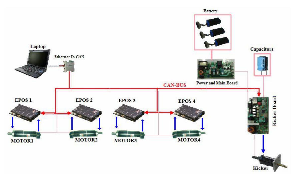
This part controls the robot movement in order to reach the target [5]. There are motor control four Maxon motor driver(EPOS) with PID controller algorithm implemented to adjust the motor velocities according to the received commands from the master processor and the motor encoders pulses [6,7]. Robot position and speed is sensed by dedicated motor encoders and sent to the high level control systems.
This multi processor control system is connected to the main and power board via a high speed CAN - Bus mechanism which will communicate with planer. All Local control is implemented on ARM Cortex M3® -LPC1768 microcontrollers to reduce the load of the main laptop PC.
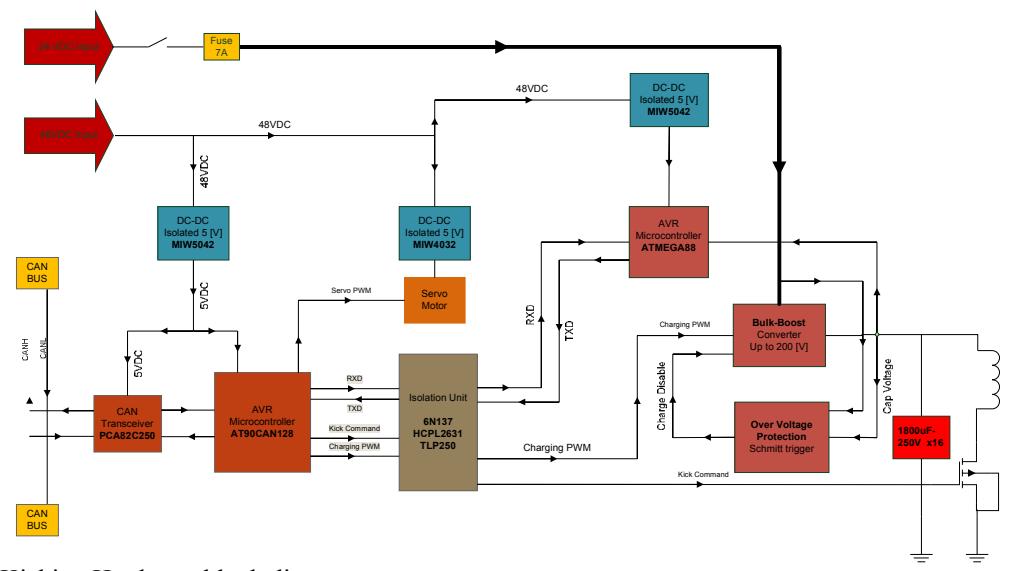
The control board of the kicker circuit is a state machine with two states. The process begins by polling Up the Kick-Flag signal by main processor (Laptop) at state one. A signal that called Kick-flag is entered to the component to set the desired kick duration. When a high logic value is read by microcontroller at state two, the kicking sequence is initiated. In this state the microcontroller holds the kick signal high for the specified period of time. Keeping up signal (Kick-command), with high level logic at the different times can be creating different Kick powers. This process takes about 18 seconds. For improving the performance of this operation, we need to reduce this time to about 5 ~ 10 seconds.
New fault finder and monitoring system give the capability of observing the required data from different parts of the robot without any connecting to the robot, also continuously reporting the available information on the CAN network and save them on SMD card. This module would be developed for new extensions like real-time system check or some manual command.
3 Software (AI and High level control):
In high level control system, we implemented some of the intelligent behavior algorithms including passing skill based on reinforcement learning, path planning with improved potential field, dribbling and fusion of information in coach box. Also navigating the robot movement to the target is also assigned to this section because of the future development of this part. We are planning to fuse the robot overall navigating system and path planning algorithm to make a trajectory planning section which would help the robot to decide the appropriate velocity during transition in the optimal path to the target.
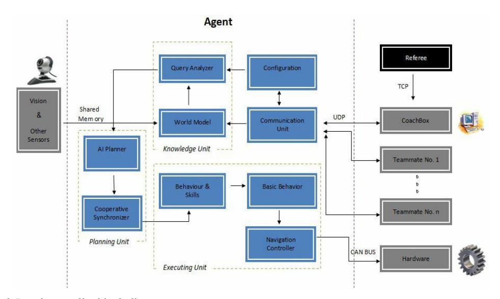
This section includes three main units: planning unit, executing unit and knowledge unit. The major task of knowledge unit is collecting sensory and vision output data, analyzing and converting them to meaningful data which are inputs of decision making sections.
Planning unit main task is to make high level intelligent decisions (commands) like track ball, hold ball and etc and orchestrates them with other teammate decisions, this part also allotted the general playing strategies of the team according to offensive and defensive states, and then sends the appropriate commands to executing unit.
In the executing unit the commands are analyzes to set of main skills, the skills are basic behaviors like: Move, Stop, Rotate, and Kick. These basic moving skills are given to navigation controller.
A new approach of AI section is changing the decision making model from decision tree to hybrid decision tree and tasks queue. In the past models, Programming the skills which should be executed sequential and scheduled were so hard but by the new method, generating most of the algorithm are simplified. In tasks queue, each task which is an object derived from secession class of "TASK" are assumed as items of constructing queue. The recommended model is the compound of the mentioned model and decision tree model. Actually, in the beginning of decision making the system decide which method is appropriate now [9].
MRL coach box was developed by Borland C++buider which shows all the robots situations and activities while playing. Also a network monitoring system is designed to check the traffic and packets on the network. For each player the parameters of player coordination,(x,y,θ), player role, player state, player color, packets speed, Vision state (if connected or not or need retune), kicker ( if on/off), motors( if on/off), robot battery voltage, laptop battery charges indicators.
The robots new main Software changes are:
- Path planning method was improved by combining Rapidly-exploring random trees with Potential-Field [10].
- Transferring source code to Qt-Framework Program, which dramatically reduces size and portables robot AI source code on different operating systems.
- Separating core application interface to facilitate its usages.
3.1 General strategy of playing (layered defense)
Our general strategy of playing is still kept layered defense because of the changes of the rules. According to the size and velocity of robots, we develop a strategy which is called layered defense. In this strategy, if a player looses to catch the ball, the other one which is called supporter would try to catch it and the ball looser robot should return back. To use the mentioned strategy there should be a communication between robots, also players should know, how many teammates are playing now? Any changing in the count of players would change the procedure of the strategy. The count is acquired by the player and coachbox doesn't have any interfere in this mission. So, firstly a multiple communication is established between teammates, then there is a function designed to count the active teammates in the software.
In addition to sharing the allotted strategy between teammates, other information like ball position is also shared between them, so if a player looses the ball position for any reason the other teammates help it to find.
To perform the strategy, imagine that there are four players in the match, the roles are assigned as: one attacker, one halfback (supporter) and two defenders. The robot which is able to fetch the ball easily is assigned as attacker and its mission is moving toward the ball, the next nearest player is assigned as halfback. Halfback (supporter) moves behind the attacker with about 1.5 meter distance from it to fetch the ball if the attacker looses it. Two defenders defense from own goal allover the two separate layers according to ball distance from own goal. The defense algorithms are such designed to minimize movements of defenders to reach their positions. The strategy is capable of extending it to play with three, two and one players.
4 Vision system and localization
Our vision system hardware, changed from last year, it is composed of a UEye camera that stands upwards with a hyperboloid mirror above it. This component provides an omni-directional vision. The output of this system is very reliable and accurate.
To process the gathered images, at first a median filter is applied in order to reduce image noises, and then the four standard color marks will be assigned to each pixel by the Color Lookup Table. The Color Lookup Table (CLT) is filled in another program, which classifies the HSL Color Space into four standard colors. This program takes some supervised samples from user to learn how to recognize the standard colors. In run time this CLT is used in an image processing algorithm to detect the ball, field, and obstacle areas in the image in real-time (50 frame/s) on the laptop computer.
Self localization is obtained through matching white lines in the camera pictures with the actual model.
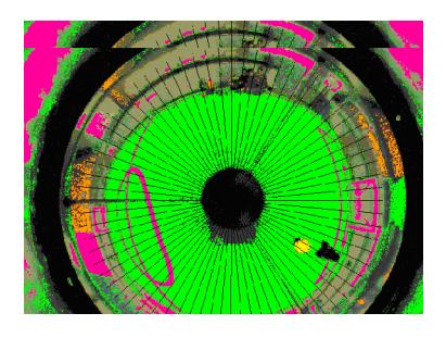
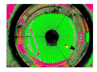
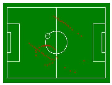
To recognize the lines in the pictures, we scan the radius of the picture from centre shown as figure 5. Then categorize the white and green connected spots, we register the center of white spot groups, which next and previous lines are green, as a part of the line and keep on this process for all radiuses, so a group of spots from the field lines are recognized shown as figure 6. At last the spots are converted from polar to Cartesian coordinate and from pixel mode to metric mode by using mirror equations shown as figure 7. Then, the position is again calculated by matching the spots with actual model of field lines shown as figure 8.
To recognize ball, first, the ball colors are segmented, circular shape segment is recognizes as the ball with designed algorithm. But now we are able to recognize any standard FIFA ball. We assigned a coefficient of error parameter to each recognized circle according to how much it is like to circle, and the circle with minimum coefficient of error is chosen. Also, we assume each black segment in the green area as an obstacle. All the above processes are done at once through entire 360 scan of the omni picture.
This year we use stereo vision system by another camera in front of the goalie to calculate the height of the kicked ball and precision enhancement of recognizing the ball far away from it. Also we are going to improve the ball detection algorithm when a small part of the ball appears in the images; this is implemented by circle fitting algorithms [11].
Successful localization could be achieved by fusing data from various sensors to reduce the uncertainty. We use a gyroscope (IMU) sensor to calculate the angles of robot to accelerate matching process.
References
- V.Rostami, S.Ebrahimijam, P.Khajehpoor, P.Mirzaei, M. Yousefiazar "Cooperative Multi Agent Soccer Robot Team," International conference in enformatika system science and engineering, Volume 9, November 25-27, 2005, ISBN 975- 98458-8-1, page 95-98.
- T.Taira, N.Yamasaki, "Functionally Distributed Control Architecture for Robot Systems".
- Brian.P.Gerkey, "Most Valuable Player: A Robot Device Server for Distributed Control," In Proceedings of the IEEE/RSJ International Conference on Intelligent Robots and Systems (IROS 2001) Pages1226-1231, Wailea, Hawaii, 29 October - 3 November, 2001.
- E. Fabrizi, G. Oriolo, S. Panzieriy, G. Ulivi "Enhanced Uncertainty Modeling for Robot Localization".
- Vahid Rostami, Saeed Ebrahimijam, Omid Sojodishijani, "Real-time distributed control system for navigating omnidirectional soccer robot,"proc. Of 15th Mediterranean Conference on Control & Automation,(MED '07). IEEE Xplore ISBN: 978-1-4244-1282-2, pp: 1-4.
- C.wurll,j.sechloen "A distributed planning and control system for industrial robots," The 5th IEEE International Advanced Motion Control Workshop (AMC'98).
- V.Rostami, O.Sojodishijani, S.Ebrahimijam, A.Mohseni "Fuzzy Error Recovery in Feedback Control for Three Wheel Omnidirectional Soccer Robot," International conference in enformatika system science and engineering, Volume 9, November 25-27, 2005, ISBN 975- 98458-8-1, page 91-94.
- Stevo Bozinovski, "Training a Football Playing Robot Using Emotion Based Learning Architecture", Workshop Proceedings A. Paiva and C. Martinho (Eds.). PP: 67-76.
- Ebrahimijam,S. , Montazeri,M., Moein,S., Rasamfard,H., Hosseini, M., "Analyzing the effect of developing emotinal intelligence on soccer robot behaviours"Proceeding of 6th International Symposium on Mechatronics and its applications, IEEEXplore ISBN: 978-1- 4244-3480-023-26 March 2009, Sharjah, UAE.
- Lavalle, S.M. (1998). "Rapidly-exploring random trees: A new tool for path planning". Computer Science Dept, Iowa State University, Tech. Rep. TR: 98–11.
- Nicolaj C. Stache, Henrik Zimmer, "Robust Circle Fitting in Industrial Vision for Process Control of Laser Welding", Proceedings of the 11th International Student Conference on Electrical Engineering, Prague MAY 2007.