Tech United Eindhoven Team Description 2011
F.M.W. Kanters, R. Hoogendijk, R.J.M. Janssen, K.J. Meessen, J.J.T.H. de Best, D.J.H Bruijnen, G.J.L. Naus, W.H.T.M. Aangenent, R.B.M. van den Berg, H.C.T. van de Loo, G.M. Heldens, R.P.A. Vugts, G.A. Harkema, P.E.J. van Brakel, B.H.M. Bukkums, R.P.T. Soetens, R.J.E. Merry, M.J.G. van de Molengraft
Eindhoven University of Technology, Den Dolech 2, P.O. Box 513, 5600 MB Eindhoven, The Netherlands
Abstract This paper describes the advances in the mechanical, electrical and software design of Tech United's Middle Size League robots for the past year. The main innovation is the renewed design of the goalkeeper. Its hardware is specifically designed to perform large sideways accelerations. Furthermore, it has been equipped with improved ball detection with laser-range scanners and an algorithm to detect the ball in three dimensional space out of front camera images.
Keywords: RoboCup Middle Size League, goalkeeper robot, 3D ball recognition
1 Introduction
Tech United Eindhoven is the RoboCup team of Eindhoven University of Technology. It consists mainly of PhD, MSc and BSc students, supplemented with academic staff members from different departments at TU/e. Tech United was founded in 2005 and the team is participating in the Middle Size league since 2006. Starting this year, the team will compete in both the @Home and the Middle Size RoboCup League. This paper describes the changes made to the mechanical, electrical and software architecture of the Middle Size League robots.
The text below is based on the status of Tech United Eindhoven in January 2011. It is part of the qualification package for the RoboCup MSL World Championships 2011 in Istanbul. First, a brief introduction of the robot platform is presented. Next, the main improvements compared to the previous team description [2] are indicated. The goalkeeper has been the most important cradle of progress for the past year, therefore it is the central theme for this paper.
2 Robot Platform
During tournaments and numerous demonstrations, the current generation soccer robots has proven to be very robust. The schematic representation published in the previous team description paper [2] still largely covers the robot, but some changes have been made to hard- and software design. Subtarget planning, for example, has been improved in a way that avoids scrum situations, positioning has been improved using a dynamic optimization based on fuzzy rules and the ball handling mechanism has been robustified.
2.1 Hardware
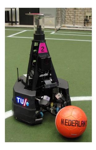
The robots of Tech United Eindhoven have been named TURTLEs (acronym for Tech United RoboCup Team: Limited Edition). A picture of the fifth generation robots is shown in Fig. 1. Three 12 V Maxon motors, driven by Elmec Violin 25/60 amplifiers and two Makita 24 V, 3.3 Ah batteries, propel the omniwheels. The TURTLEs have an active ball handling mechanism which enables them to control the ball when driving forwards, while turning and even when driving backwards [3]. The solenoid shooting mechanism, which is powered by a 450 V, 4.7 mF capacitor, provides and adjustable, accurate and powerful shot [6]. To acquire information on the surroundings, the robot has two cameras, a front camera and an omnivision camera. The high speed front camera can accurately track the ball, and is able to see the ball when it is in the air. The omnivision camera has a 360◦ view which gives information on the positioning and the surroundings. An electronic compass is used to distinct the own side of the field from the opponent side, which cannot be extracted from the vision system, because the field is symmetric with respect to the middle line.
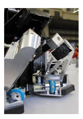
One significant drawback, which caused several missed shots during the world championship in Singapore, was the reliability of the ball handling mechanism. Collisions with opponents frequently broke the rods in the construction that carried the wheels for the active ball handling. After analysis with high speed camera shots of collision tests, a slight twist of the rods appeared to cause to failure. To deal with this issue the ball handling mechanism has been redesigned, such that it is more robust for on ball collisions (Fig. 1). Cutouts in the new mechanism allow a laser scanner, which is located behind the ball handling mechanism, to measure the ball position when the ball is in front of the TURTLE.
2.2 Data-Acquisition and Software
To acquire data and for motion control, the robots are equipped with EtherCAT devices [5, 7], which are connected to the onboard host computer via ethernet. Each robot is equipped with a mini-PC running a preemptive Linux kernel. The robot software is automatically generated from Matlab/Simulink models via the RTW toolbox. This year, a new multitasking target for automatic code generation with Matlab's Embedded Codes has been developed, which supports thread-safe asynchronous tasks running at arbitrary rates. In this way, a modular software framework is obtained. The software is divided in three main parts, namely a vision, worldmodel and motion module. While vision and worldmodel modules both run at 30 Hz, the motion module uses a much higher sampling rate of 1000 Hz. The vision module provides localization of ball and TURTLEs. Hereafter the worldmodel combines information from all robots to get an estimation on peer and opponent players. The motion module contains the strategy and the actual motion controllers of the TURTLEs.
3 Main Improvements 2011
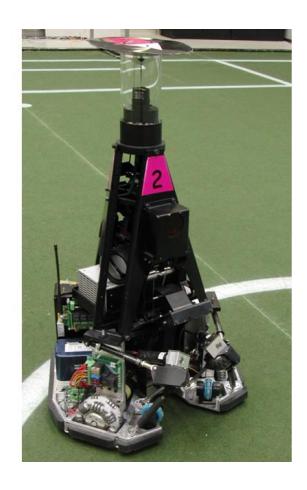
Johan Cruijff, a famous Dutch soccer player once said: If you score one goal more than your opponent, you win. So though the right tactic may seem trying to score as many goals as you can in a match, this quote also implies that defence is as important as offence in soccer. With an average of 8.4 goals per match in Singapore, the TURTLEs scoring abilities were quite good. The defense, however, has been poor, especially the goalkeeper. Therefore Tech United has decided to develop a new goalkeeper (depicted in Fig. 2).
One aspect of building a good goalkeeper, is obtaining a good measurement of the ball position. Due to the development of strong kicking devices, the ball can move at high speeds up to 10 m/s. Therefore fast and accurate sensors are required to measure the ball position. Another aspect is that a goalkeeper needs to be very fast in order to be at the right position on time. In this section the new motion platform and the improved sensor system, consisting of an improved vision system combined with laser sensors, is presented.
3.1 Keeper Hardware
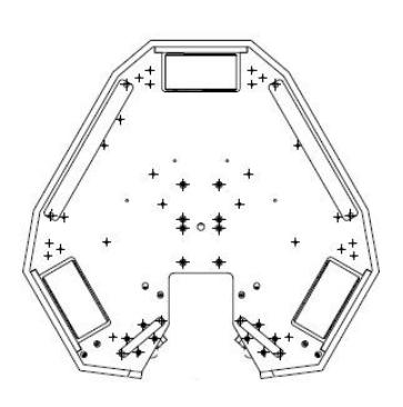
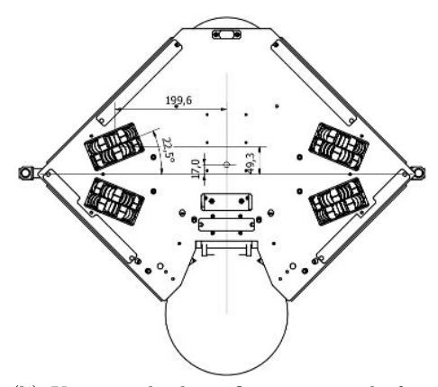
At present, the holonomic motion platform of the TURTLE has three omniwheels, as depicted in Fig. 3(a). Using this configuration motions to the left or right are not very fast, since only the motor at the back is aligned with this direction of motion. For the new goalkeeper, a configuration as depicted in Fig. 3(b) is designed. It can be seen that the new platform has four wheels that are almost completely perpendicular to the front of the robot. For a goalkeeper that mostly moves sideways, this is an ideal configuration. The choice of an extra wheel is justified, since the increase in mass of approximately 2 kg is easily compensated by a 33 % increase in power. The target acceleration of the keeper is 0.9 g. This implies that the keeper is able to travel from the center of the goal to the goalpost in 0.38 s from standstill. It will accelerate to 3.3 m/s, assuming the ground surface can deliver the required friction.
Although the extra wheel gives extra power, the control of the goalkeeper is a bit more complicated. The system has four inputs, which are the motor forces F1, F2, F3, F4, and four encoder outputs e1, e2, e3, e4, that have to be related to the forces Fx, F$^y$ and the torque TRz to steer the robot to a desired pose x, y, φ. First, the decoupling of the robot is designed such that separate controllers can be designed for the x, y, φ direction. A schematic representation of the decoupling is shown in Fig. 4. In this figure, T$^u$ represents the input transformation matrix, while T$^y$ represents the output transformation matrix.
The extra wheel causes the platform to be overdetermined, in the sense that certain combinations of inputs counteract each other. The inverse of the input transformation matrix can be used to show this. The null space of this matrix is found to be
$$\mathcal{N}(T_u^{-1}) = \begin{bmatrix} -1 \ 1 \ -1 \ 1 \end{bmatrix}^T.$$
In that case the motors try to 'compress' or 'stretch' the robot, which is of course impossible and only causes loss of energy and slipping wheels. However, a proper choice of the decoupling matrices will not generate inputs in this direction. When the decoupling is not perfect, e.g. due to errors in the assumed geometry, this phenomenon could occur. Since the fabrication process of the goalkeeper is not finished at this moment, no experimental results have been obtained yet.
The extra wheel also brings an advantage. Three sensors are sufficient to determine the robot position. The information from the fourth sensor can be used to validate whether the wheels of the robot are slipping. Since the platform is rigid, the velocities of the wheels must satisfy
$$v_1 + v_3 = v_2 + v_4$$
or else the wheels are slipping. In the planned experiments this property and the motion control will be investigated further.
Besides the new wheel layout, the rack of the keeper that is used to block the ball is improved (visible in Fig. 2). The current goalkeeper has one rack that can move to the left or right. In the new design, the rack is split in a left and right part, thereby reducing the moving mass which results in a faster system.

3.2 Keeper Vision
As stated before, fast and reliable ball detection is crucial for a keeper robot. The vision system (featuring a frontcam and an omnivision camera) plays a key role in this. In the next paragraph, 3D ball detection out of omnivision will be described, followed by a paragraph about ball detection from front camera images. Combined with data out of the laser range scanners (section 3.3), this should yield enough information to detect and stop both high and low shots on goal.
3.2.1 Omni-based 3D ball detection
The previous goalkeeper only used color segmentation in combination with two mappings in order to determine the ball coordinates in two dimensions. These two mappings are: (i) A mapping f(p) from image coordinates to metric coordinates who are also used for localization. (ii) A mapping g(y) from metric coordinates to the ball radius $r_b$ in image coordinates assuming that the ball is lying on the ground. In a sequence of algorithmic steps, 2D ball recognition is best described as:
- Mapping from pixel distance to metric distance projected onto the ground: $y_l = f(p)$
- Correction for ball size: $y_c = c \cdot y_l$ , with c constant.
- Check validity by comparing $g(y_c)$ with the measured radius $r_b$ of the candidate ball blob.
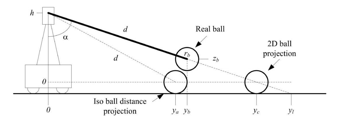
For a goalkeeper this two dimensional information alone is not enough, it should be able to react on high balls as well. An extension towards three dimensional ball coordinates therefore is desirable (Fig. 5). The method described below requires no additional calibration steps, which obviously is an advantage. A slight disadvantage is that it only works for balls below the height of the omnivision system $(z_b < h)$ . Nevertheless, ball detection will be more robust for bouncing balls which results in improved behavior.
- Compute the iso ball distance projection from measured ball radius: $y_a = g^{-1}(r_b)$
- Compute the distance to the ball: $d = \sqrt{h^2 + y_a^2}$ 3. Compute the ball height: $z_b = h(1 \frac{\sqrt{d^2 + h^2}}{\sqrt{y_c^2 + h^2}})$ 4. Check validity: If $-z_{thr} < z_b < z_{thr}$ then $z_b = 0$ , if $z_b > z_{thr}$ then ball is in the air, if $z_b < z_{thr}$ then discard ball candidate
3.2.2 Real time arbitrary ball detection using an FPGA platform
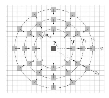
When no specific ball color can be assumed, the best visual clue to detect a ball in a still image is the roundness of the ball. Roundness of an object in an image is a property of the boundary of the object, i.e. the contour or edge. The human visual system is very sensitive to edges or contours in an image and therefore a robust method inspired by the human visual system is proposed to find round objects in an image. In the human visual system, there are specific cells that fire when a stimulus with a certain orientation is presented [4]. It has been shown that there are cells for all different orientations and these cells are ordered in a structured manner. There is also communication between these cells that can reinforce or suppress the cell's response depending on the response of other cells [1]. This principle is used in our circle detector. Fig. 6 shows this schematically. Each pixel (or cell in the human visual system) has surrounding pixels that are sensitive to a certain direction (towards the center pixel). The sensitivity can be modeled by the derivative in the direction of the center pixel.
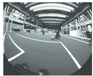
The sum of the responses for pixels on a certain circle with radius r gives a notion of the confidence that at a certain pixel Pi,j there is a circle with radius r present. This can be repeated for several radii and the radius with maximum confidence can then be selected. The confidence of this radius will be assigned to the pixel, together with the optimum radius itself. This is repeated for each pixel and finally the pixel with the highest confidence most likely represents the center of the ball in the image.
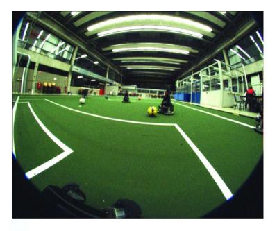
In order to be able to detect all balls that are directed towards the keeper, a large field of view is desired. For this purpose a Fujinon lens with an angle of 185◦ is used. Fig. 6 shows an example image of the soccer field with some soccer balls. With such a wide angle everything in front of the robot can be seen by the front camera, which solves many of the problems that would occur while using a camera with a smaller lens angle.
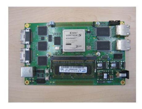
Although the principle of the ball detection algorithm is simple, the implementation is computationally very time consuming. For each pixel the gradient must be calculated and next the derivative in a certain direction has to be calculated for a number of pixels around the center pixel. In computational complexity this equals multiple 2D non separable spatial convolutions. Therefore a fast hardware implementation based on FPGAs is used (in this case a Xilinx Virtex5 SX50T). Initially this FPGA vision platform (Fig. 7) is developed for the goalkeeper alone, in the future it will be implemented in all TURTLEs.
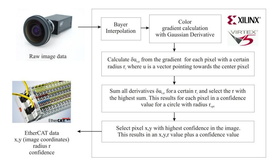
The advantage of an FPGA is that the data stream can be optimized and that many parallel computation blocks can be used. For instance, the gradient of the image can be calculated in a streaming fashion using a number of MultiplyAdd blocks and some line buffers. Furthermore, only a limited number of lines need to be in the memory at the same time. Comparable, the derivative in the direction of the center pixel can be calculated with a limited set of MultiplyAdd blocks and some line memory. A maximum can be calculated on the fly and therefore the total delay of the algorithm is minimized. The final ball position and radius are available only a few clockcycles after the camera has sent the image frame, since it is not necessary to buffer the complete frame which is the case for a normal PC implementation. A schematic overview of the complete algorithm is shown in Fig. 8. The raw camera data is an input of the Xilinx Virtex5 FPGA, where first a Bayer interpolation is performed. After this step the gradient is calculated and afterwards the local derivatives for each point in a circle around the present pixel are calculated. Finally these derivatives are summed and the best candidate for the ball is selected. The resulting ball position, radius and confidence are send via the EtherCAT interface to the robot control block. The conversion from image coordinates with a radius to real world coordinates is performed on the PC, which also corrects for the distortion of the wide angle lens.
3.3 Laser Range Finders
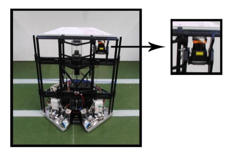
To improve the quality of the world model, Laser Range Finders (LRF) are added to the field players and the keeper. A Laser Range Finder can measure the distance to objects with a high accuracy over a long range. It does so by measuring the phase shift of the emitted and received light from an infrared laser. The used LRF is the UTM-30lx manufactured by Hokuyo, which can be seen in Fig. 2.
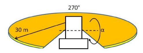
The range of this sensor is 30 meters and the viewing angle is 270 degrees (Fig. 9). The angular accuracy of the measurements is 0.25 degrees and the spacial accuracy is distributed with σ < 10 mm for the range below 10 meters and σ < 30 mm in the range of 10 − 30 meter. An advantage of using a Laser Range Finder is that the viewing area in radial direction is relatively large. Another advantage is the high depth resolution, compared to a standard or stereo vision camera. A big disadvantage is the impossibility to measure in three dimensions. Because the LRF only measures in a two dimensional plane, the sensor has to be tilted in order to track high balls.
3.3.1 3D ball estimation
To detect lob balls, we need extra sensor information above the height of the omnivision. For this purpose, a Laser Range Finder is attached to the highest point of the keeper. It is slightly tilted upwards to have a clear line of sight above the robots. When the ball disappears out of the view of the omnivision, the laser scanner can see the ball passing through his viewing area. After the detection of the ball, the LRF is tilted further upwards with a servo to measure additional positions of the ball in the air (angle α in Fig. 9). With these points, the complete path of the ball can be calculated using a parabolic fit. After the direction is calculated, the keeper and other players can position to intercept the ball when coming down, and into the viewing area of the omnivision.
3.3.2 Global position estimation
The keeper has additional Laser Range Finders in the back and the front. It uses these sensors to accurately estimate its own position with respect to the goal and the position of the field robots with respect to himself. Due to the high spatial accuracy of the LRF, the accuracy of the world model can be improved by these measurements. The information from the other LRF (the one tracking the ball) is also defined relative to the keeper coordinate frame. Therefore the improved accuracy of the keeper position estimation increases the position of the 3D ball estimation as well.
3.3.3 Improve accuracy for passes
The field robots are equipped with a LRF at ground level, to track opponents and the ball when on the ground. The omnivision suffers from distortions during the interception of a pass due to the fact that the robot slightly tilts when accelerating to intercept the ball. Because LRF measurements suffer less from the tilting of the robot, the data from the LRF is used to improve the interception of the ball during a pass.
4 Conclusions
With the new and improved goalkeeper robot, Tech United is aiming to significantly increase its defensive capabilities. Important are the much improved motion capabilities, but also the improvements in 3D ball recognition. Motion is, using an adapted configuration of the omnowheels, particularly focused on high sideways accelerations. Three dimensional ball recognition consists of three inputs; (i) 3D ball recognition out of omnivision, (ii) 3D ball recognition out of frontcamera and (iii) ball tracking using laser range finders. Together these inputs should provide enough data to timely identify a shot on goal. Offensively the renewed design of the ball handling mechanism should result in an increased robustness and therefore in more goals.
References
- W. Bosking, Y. Zhang, Y. Schofield, D. Fitzpatrick, Orientation selectivity and the arrangement of horizontal connections in the tree shrew striate cortex, J.Neuroscience 17 (1997) 2112–2127.
- J. de Best, D. Bruijnen, R.Hoogendijk, R. Janssen, K.J.Meessen, R. Merry, M. van de Molengraft, G. Naus, M. Ronde, Tech United Team Description Paper, RoboCup, 2010.
- J. de Best, M. van de Molengraft, M. Steinbuch, A novel ball handling mechanism for the robocup middle size league, Mechatronics 21(2).
- D. Hubel, T. Wiesel, Receptive fields, binocular interaction and functional architecture in the cats visual cortex, J. Physiol 160 (1962) 106–154.
- D. Jansen, H. Buttner, Real-time ethernet the EtherCAT solution, Computing & Control Engineering Journal 15 (1) (Feb.-March 2004) 16–21.
- K. Meessen, J. Paulides, E. Lomonova, A football kicking high speed actuator for a mobile robotic application, Proceedings of the 36th Annual Conference of the IEEE Industrial Electronics Society (2010) 1659–1664.
- S. Potra, G. Sebestyen, EtherCAT Protocol Implementation Issues on an Embedded Linux Platform, Automation, Quality and Testing, Robotics, 2006 IEEE International Conference on 1 (May 2006) 420– 425.