MRL Middle Size Team: Robocup2016 Team Description Paper
A.Karambakhsh, H.RasamFard, A.H.MaaroofMashat, S.Ziyadloo, M.Yeganehdoost, S.E.Marjani, M.AmirSardari, M.J.Asnaashari Amiri, A.Abbasian Amiri, M.Mahdizadeh, M.Hajikarimian, N.Montazeri
Mechatronics Research Laboratory, Islamic Azad University of Qazvin - IRAN
Abstract The paper mainly describes the implementation of our middle-size league robot team "MRL" for Robocup 2016 with the improvements made since the previous years. Our major concerns for this year's competitions have been developing a new feed forward control system, designing a new Omni vision structure, designing a new ball handling system, also developing a newfeature in AI software which is an accurate role assigner.
1 Introduction
The MRL middle size team has started its work at Mechatronic Research Laboratory of Azad University of Qazvin since Aug 2003. This team aims at establishing an intelligent control method for autonomous multi-robot systems in dynamic uncertain environment. MRL has begun the research and work in MSL since 2004. Our first official participation was during Robocup 2005 competitions in Osaka and then Robocup 2006 in Bremen. We optimized hardware, control and software system for Robocup 2008 and designed robust system for Robocup 2009 in Graz, as a result we find ourselves between four top teams. In Robocup Singapore 2010 competitions we got the first place of technical challenge and again fourth place of league competitions. Also, we got second place of free challenge and fifth place of league in Robocup Turkey 2011 competitions. After a year of hard work, we managed to get the second place of league in Robocup Mexico City 2012 competitions. Luckily another achievement of the team was getting the 1st place of technical challenge in Robocup Of China in 2015. We believe that, the Intelligent, cooperative and adaptive behavior of the robots is very important factor for a team success. With this regard our research is continuously focused on: reliability, sensor fusion, dealing with uncertainty of environment for the robots, world modeling and dealing with missing information. In the following sections we briefly explain current status and new achievements of our team.
2 Hardware and mechanical features
We designed4-wheel omnidirectional robot which is equipped with MAXON EC 200 watt brushless motors which provides more speed and easy to control [1]. Main processor is Lenovo X200 notebook PC and electronic equipment are developed with ARM Cortex M3® -LPC1768 microcontrollers with high speed CAN-bus. This year we designed a new ball handling system and new Omni vision structure which is explained in the following sections.
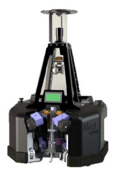
Table 1. Hardware specification of the robot
| Items | Description | |
|---|---|---|
| Platform | 4 wheel Omnidirectional |
|
| Max speed | 3.5 m/s | |
| Max acceleration | $4 \text{ m/s}^2$ | |
| Kicker | Electromagnetic | |
| Weight | 40 Kg | |
| Laptop | Lenovo X200 | |
| Camera | uEye UI-2210-C | |
| Image processing | Omni directional mirror | |
| Other sensor | IMU and IR | |
| Controller | Neural Network PID | |
| Spin back | Active 60watt 24V DC motor |
2.1 New ball handling structure
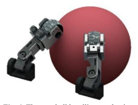
This year, a new ball handling system has been developed as shown in figure4that enablesthe robot to control and hold the ball while it's driving in any direction even it's turning around. This generation of spin back has five degrees of freedom which enables to set their position to have optimized performance of the ball handling system according to different conditions during match.
2.2 New ball Kicker
Kicker changes in 2 cases consider us:
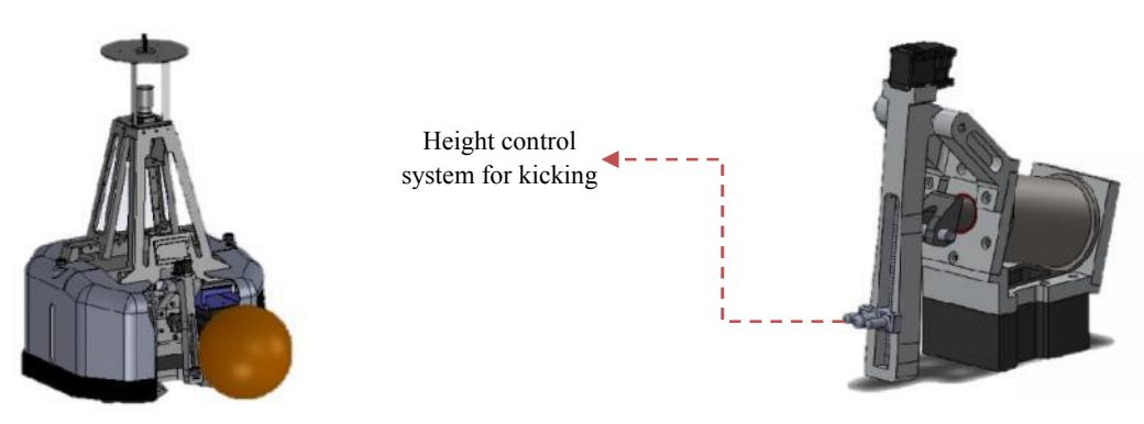
- Kicking height control system for a variety of pass
- Increase the contact area with the ball
The new design allows you to change kicker'sheight, this topic causes the progress of passing of between robots. The system uses the Ball Screw and a Dynamixel motor Kicker given the possibility to change the height, according to Dynamixel engine, allows you to determine the required height as well as the feedback we have received your system performance. With design and construction of the piece is to establish contact with the ball most of the trident. This system makes it possible to establish the highest level of contact with the ball and thus prevent the diversion of the ball and hit it straight.
2.3Wheels
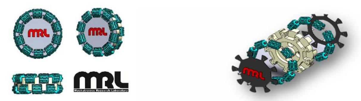
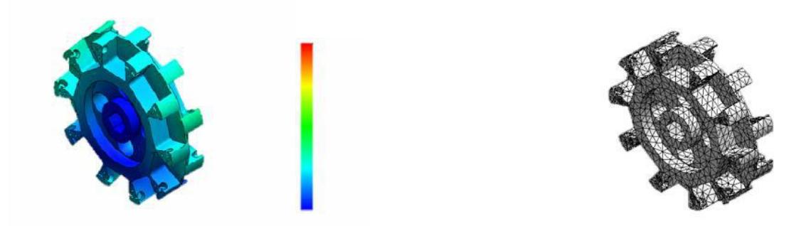
As shown in figure 5, changes in wheels and Increase the number of rollers in the environment of wheels, Causes the robot to minimize vibration, In addition, during the game is not necessary to correct wheels.
2.3 Electrical Design
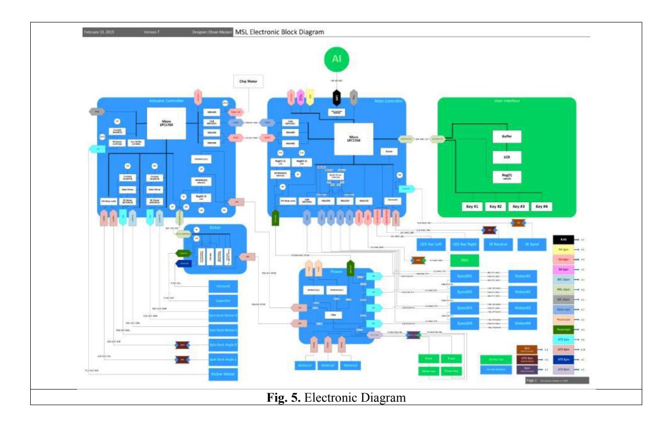
The new electrical system of MRL team has been designed and developed continuously for more than 2 years. Our system consists of power, Kicker, monitoring, FDS, E2C and DMS boards; this approach simplifies the repairing process especially during the matches. Figure 5 shows the diagram of our Electric part.
The major changes during the last year are:
- Local processors are changed
- Removing onboard processors and reducing the number of them into two processors
- Reduction of information volume on CAN BUS because of some low level calculation and the number of communication nodes
- CAN BUS drivers are separated from communicative CAN BUS trough processors to prevent data loss and facing error
- Reduction of EPOS for spin backs motors
- Direct communication of processors with Ethernet BUS and CAN
- Codification of wiring to troubleshoot errors by coding table
The same as previous years, we decided to utilize ARM7 microcontroller. It was selected for several reasons such as its powerful debugging capabilities and low-power design of ARM architecture. In addition, the ARM7 with TDMI- S core is one of the best choices for system control. Hence, only real-time tasks such as motor driving are executed in high level and all remained parts are implemented in ARM7 microcontroller. We used ARM7-TDMI core and developed the project in KEIL software.
In the following sections we briefly explain current electronic accessories.
2.3.1 Main controller board
The main board is responsible for communicate with laptop by Ethernet protocol and communicate with operator port by CAN protocol. Also it's responsible for communication of main motors drivers and required signals to communicate with user interface and LED strings. This board also achieves the information of IMU by serial.
2.3.2 Actuator controller board
There are four BLDC (Brushless DC) motors for each robot which are MAXON EC 200watt brushless motors and two DC 60watt motors for the dribbler. Four motors are controlled by Epos driver that have an ability to manage low level control where directly receives speed from high level system. In new circuit, spin backs motors are controlled by operator board.
2.3.3 Power board
This module has a responsibility to distribute the power for all subsystems and turning the systems on and off. Also many parts same as IR sensors spin-back's motors and monitoring LEDs are controlled in this module.
2.3.4 Kicker Board
The kicker board is designed to control the high voltage. It has one MOSFET for charging and four for kicking. The board also contains MOSFET driver to turn on and turn off the MOSFET in nanoseconds which prevents damaging them. The control board of the kicker circuit is a state machine with two states. The process begins by polling Up the Kick-Flag signal by main processor (Laptop) at state one. A signal that called Kick-flag is entered to the component to set the desired kick duration. When a high logic value is read by microcontroller at state two, the kicking sequence is initiated. In this state the microcontroller holds the kick signal high for the specified period of time. Keeping up signal (Kick-command), with high level logic at the different times can be creating different Kick powers. This process takes about 18 seconds. For improving the performance of this operation, we need to reduce this time to about 5 ~ 10 seconds.
2.3.5 User interface board
For changing the states of robot we consider some push keys and LCD with ability to monitor and change in system. In this case we could informed about all subsystem's state and debug them online in a very low period of time.
2.3.6 Battery
Power supply in our robot is departed in 2 sections, boards and motors power supply. Board power supply contains 6-cells and motors power supply contains 12-cellswhere robots can run for half game with these batteries. These batteries are lithium polymer (LiPo) battery, with capacity of 5000 mAh. When voltage of batteries reduces, the robot switches to sleep mode and stops working. Of course it was monitored by LEDs before reaching to low battery state and by a buzzer to show the critical state.
2.3.7 Ball detection sensor
For recognizing the ball position in dribbler and distance of the ball from the dribbler, two IR transmitters and receiver sensors were used. This module is useful when robot tries to get accurately behind the ball.
2.3.8 Current Sensor
For power management system, detecting over current, avoiding motor damage, battery current limitation, control usage sin plunger and safety of kicker board, these sensors was utilized. Sometimes damaged happened in devices caused over current that destroy Electrical devices so we decided to use ACS712 as a current control to prevent these damages.
3.1 High Level Control
The high level control system receives predicted data from vision software and destinations from AI planner module and make robot go to its destinations. So, the important part of control system is a path planning algorithm and we used the VORONOIaspath planning algorithm [2]. MRL team uses the assistance of multi-agent path planning algorithms in order to minimize teammates' collision.
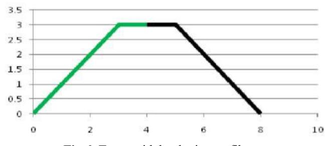
The control system will find the path (VORONOI) by using start position, end position, initial velocity along x and y axis and direction of starting point and ending point. Using the result path usage time will be calculated in order to generate the velocity command which will be sent to the robot. The velocity command is generated separately for each point along the trajectory according to the frame rate. Each frame has its own velocity command. The velocity profile is generated by using Bang-Bang algorithm and makes a robot trapezoidal velocity as shown in figure 6.
The robot can move with a faster velocity when it moves forward or backward and slower velocity when it moves to left or right direction. The binary search is used to find the different of velocity to time. The proper velocity is separated in x and y direction. After calculation along x and y direction, the maximum total time usage is selected in order to guarantee the robot motion. For example, if the total time usage along x- axis is greater than along y-axis, the trajectory time constrain is the total time along x- axis. The velocity that is generated for a robot in x direction will use a proper velocity along x-axis (maximum) and the velocity in y direction will use smaller value than the value that is calculated from previous step in order to make the robot moves smoothly. Also angular velocity time must be equal or lower than maximum time that calculated in the last step. This algorithm is calculated online at every frame and does not have any feedback from robot velocity because it's a feed forward algorithm.
3.2 Software architecture
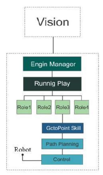
The software architecture for our decision making system consists of three parts: Plays, Roles and Skills. Skills are any single tasks that robots can do. For example "go to point" is a skill. Each player in a real soccer game has a role like defender, forward, goalie and etc. Compared with real soccer game each robot can change its role at the right time. Switching time is an important approach to manage robots, for this reason we need an accurate role assigner. Hence, we have developed anew role assigner module that assigns role to the robot according to game state and cost of roles for each robot.
3.3Role assigner
The Hungarian method is a combinatorial optimization algorithm that solves the assignment problem is polynomial time and which anticipated later primal-dual methods. MRL team uses the Hungarian algorithm to robot role assignment. Each robot has an specific cost for each role that the costs are calculated in the roles cost-function. Suppose that we are given a nonnegative n×n matrix, where the element in the i-th row and j-th column represents the cost of assigning the j-th job to the i-th worker. We have to find an assignment of the jobs to the workers that has minimum cost. If the goal is to find the assignment that yields the maximum cost, the problem can be altered to fit the setting by replacing each cost with the maximum cost subtracted by the cost.In this simple example (Table 2) there are three Robots. One of them is goalie, defender, and the third is forward, but each of them demands different cost for the various roles. The problem is to find the lowest-cost way to assign the roless. The problem can be represented in a matrix of the costs of the robots doing the roles. In this case robo1 take goalie, robot 2 take defender and the robot 3 take forward.
Table 2. Use Hungarian algorithm to role assignment
| Goalie | Defender | Forward | |
|---|---|---|---|
| Robot 1 | 1 | 2 | 5 |
| Robot 2 | 4 | 3 | 4 |
| Robot 3 | 3 | 1 | 1 |
4 Vision system and localization
Our vision system hardware is composed of a UEye camera that stands upwards with a hyperboloid mirror above it. This component provides an Omni-directional vision. The output of this system is very reliable and accurate. To process the gathered images, at first a median filter is applied in order to reduce image noises, and then the four standard color marks will be assigned to each pixel by the Color Lookup Table. The Color Lookup Table (CLT) is filled in another program, which classifies the HSL Color Space into four standard colors. This program takes some supervised samples from user to learn how to recognize the standard colors. In run time this CLT is used in an image processing algorithm to detect the ball, field, and obstacle areas in the image in real-time (50 frame/s) on the laptop computer.
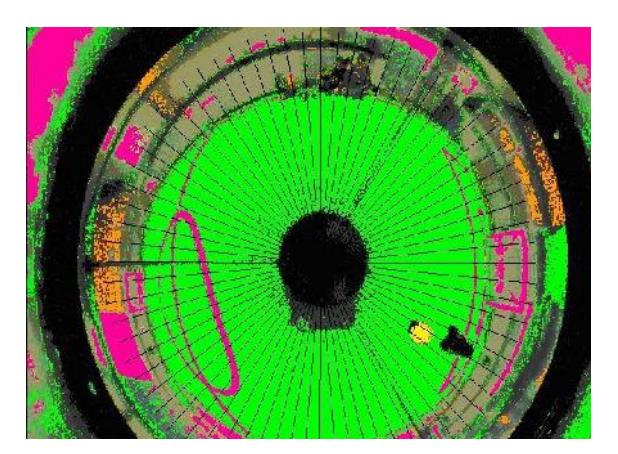
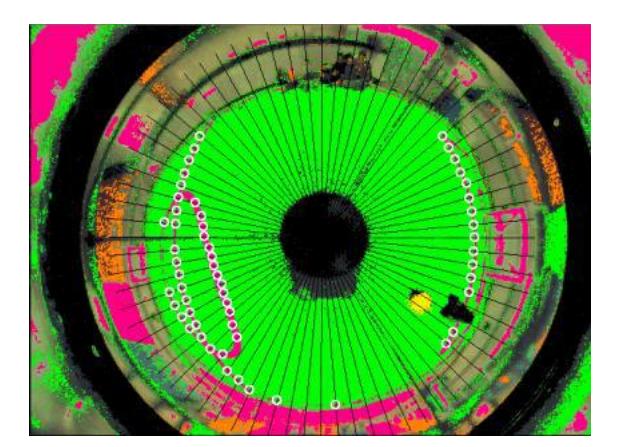
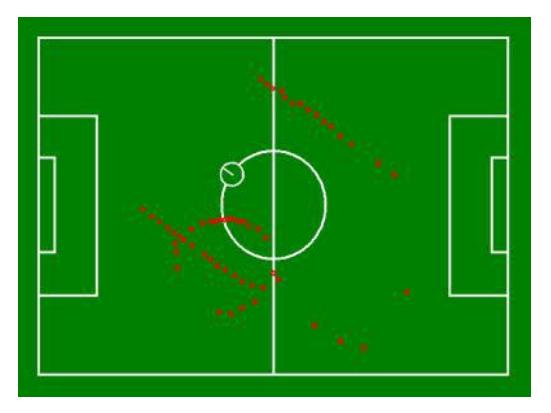
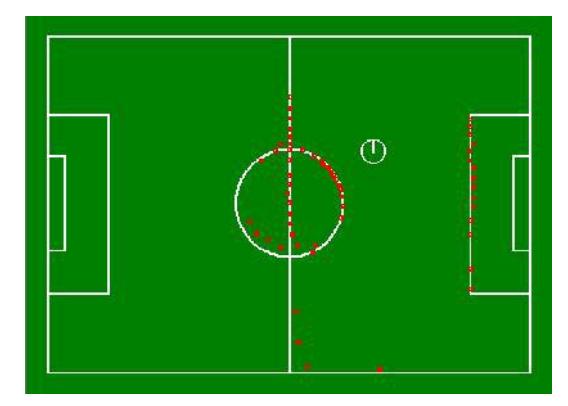
Self-localization is obtained through matching white lines in the camera pictures with the actual model. To recognize the lines in the pictures, we scan the radius of the picture from center shown as figure 8. Then categorize the white and green connected spots, we register the center of white spot groups, which next and previous lines are green, as a part of the line and keep on this process for all radiuses, so a group of spots from the field lines are recognized shown as figure 9. At last the spots are converted from polar to Cartesian coordinate and from pixel mode to metric mode by using mirror equations shown as figure 10. Then, the position is again calculated by matching the spots with actual model of field lines shown as figure 11.
To recognize ball, first, the ball colors are segmented, circular shape segment is recognizes as the ball with designed algorithm. But now we are able to recognize any standard FIFA ball. We assigned a coefficient of error parameter to each recognized circle according to how much it is like to circle, and the circle with minimum coefficient of error is chosen. Also, we assume each black segment in the green area as an obstacle. All the above processes are done at once through entire 360 scan of the Omni picture.
This year we use stereo vision system by another camera in front of the goalie to calculate the height of the kicked ball and precision enhancement of recognizing the ball far away from it. Also we are going to improve the ball detection algorithm when a small part of the ball appears in the images; this is implemented by circle fitting algorithms [3].
Successful localization could be achieved by fusing data from various sensors to reduce the uncertainty. We use a gyroscope (IMU) sensor to calculate the angles of robot to accelerate matching process.
4-2 Localization
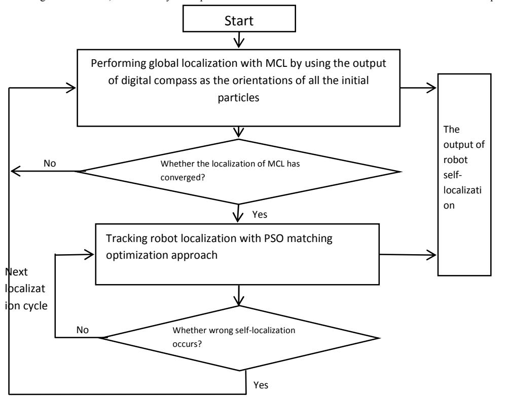
localization and mapping, are important capability of middle size robots. Localization are done by some sensors but since there is a problem which is uncertainty, this issue is turned into a complex problem. The localization process which is used in MRL robots are shown in figure 12 that is in three phases:
- 1-Pre Processing
- 2-Global localization
- 3-Optimization
At feature extraction phase, scheme of field is available by using inline vision system includes a camera and omnivision mirror. Then image will be entered into separation process based on colors codes. After this process, some white samples which are devoted to white lines of the field will be extracted, are exactly the point features. Since the point positions of previous step are available at camera coordinate system with assistance of outer and inner terms of camera and omnivision mirror surface equations, the positions of the points will be turned into field coordinates,
In global localization phase, with the assistance of montokarlo localization, an estimation of robot position in the field will be achieved. Inoptimization phase, by using swarm optimization algorithm. By matching the points with the field borders, the accurate robot position will be discovered. Also in order to reduce the noises that would be the result of collision and high speed during the play, Kalman Filtering is used.
According to the results, the accuracy and speed of the recommended method has been enhanced about 15 percentthan other methods.
Lu, H., Li, X., Zhang, H., Hu, M., &Zheng, Z. (2013). Robust and real-time self-localization based on omnidirectional vision for soccer robots. Advanced Robotics, 27(10), 799-811.
4-2Xtion
Ball detection on field-players is handled by the Omni vision module. In addition we provided Xtion camera. This additional sensor allows us to accomplish improved performance in object recognition, human robot interaction, manipulation, gesture recognition and navigation.
References
- V.Rostami, S.Ebrahimijam, P.Khajehpoor, P.Mirzaei, M. Yousefiazar "Cooperative Multi Agent Soccer Robot Team," International conference in enformatika system science and engineering, Volume 9, November 25-27, 2005, ISBN 975- 98458-8-1, page 95-98.
- J.W. Choi, R.E. Curry, G.H. Elkaim, Real-time obstacle avoiding pathplanning for mobile robots, in: Proceedings of the AIAA Guidance,Navigation and Control Conference, AIAA GNC 2010, Toronto, Ontario,Canada, 2010.
- Nicolaj C. Stache, Henrik Zimmer, "Robust Circle Fitting in Industrial Vision for Process Control of Laser Welding", Proceedings of the 11th International Student Conference on Electrical Engineering, Prague MAY 2007.