Tech United Eindhoven Team Description 2016
Cesar Lopez, Ferry Schoenmakers, Koen Meessen, Yanick Douven, Harrie van de Loo, Dennis Bruijnen, Wouter Aangenent, Bob van Ninhuijs, Matthias Briegel, Patrick van Brakel, Jordy Senden, Robin Soetens, Wouter Kuijpers, Joris Reijrink, Camiel Beeren, Marjon van 't Klooster, Lotte de Koning, René van de Molengraft
Eindhoven University of Technology, Den Dolech 2, P.O. Box 513, 5600 MB Eindhoven, The Netherlands
www.techunited.nl · http://www.roboticopenplatform.org/wiki/TURTLE · http://techunited.nl/en/turtle-qualification · http://www.visual-analytics.eu/ · https://dev.windows.com/en-us/kinect/hardware · http://www.nvidia.com/object/jetson-tk1-embedded-devkit.html
Abstract In this paper we discuss the progress in mechanical, electrical and software design of our middle-size league robots over the past year. Recent progress in software includes improved perception methods using combined omnivision of different robots and integrating the Kinect v2 camera onto the robots. To improve the efficiency of shots at the opponents goal, the obstacle detection is improved. Furthermore, a new shooting skill is being developed as well as a new visualisation tool.
1 Introduction
Tech United Eindhoven is the RoboCup team of Eindhoven University of Technology. Our teams consists of PhD, MSc, BSc students and old TU/e students, supplemented with academic staff members from different departments. The team was founded in 2005, originally only participating in the Middle-Size League (MSL). Six years later service robot AMIGO was added to the team, which participates in the RoboCup@Home league. Knowledge acquired in designing our soccer robots proved to be an important resource in creating a service robot.
This paper describes our major scientific improvements over the past year. It is a part of the qualification package for the RoboCup 2016 World Championship in Germany and contains five main sections. Section 2 we introduce our current robot platform followed by the improved robot perception in Section 3. Here we focuss on the improved ball position estimation using omnivision and the integration of the Kinect v2 onto the robots. Furthermore, the improved obstacle detection is explained in Section 4, enabling for a better estimation of the goalkeeper position. Section 5 introduces a new shooting skill and finally a new visualization tool is discussed.
2 Robot Platform
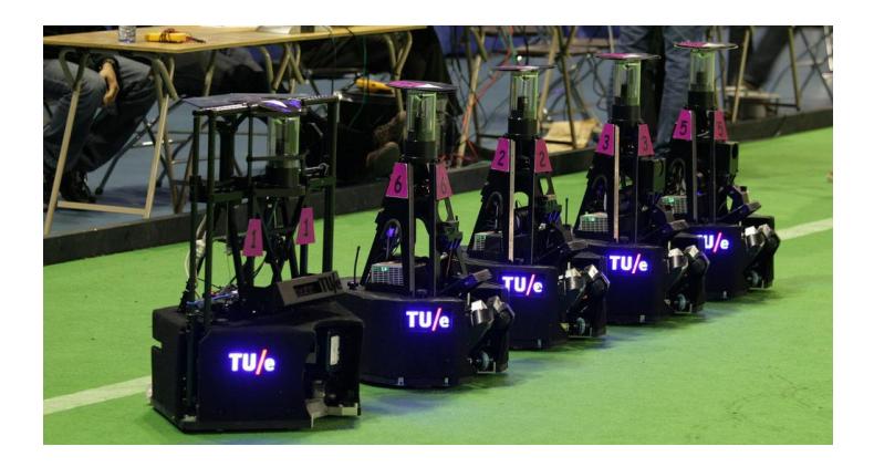
Our robots have been named TURTLEs (acronym for Tech United RoboCup Team: Limited Edition). Currently we are employing the fifth redesign of these robots, built in 2009, together with a goalkeeper robot which was built one year later (Figure 1). Development of these robots started in 2005. During tournaments and demonstrations, this generation of soccer robots has proven to be very robust. The schematic representation published in the second section of an earlier team description paper [5] covers the main outline of our robot design. The major change regarding the robot platform is the upper body design of the robot due to the integration of the Kinect v2 camera.
A detailed list of hardware specifications, along with CAD files of the base, upper-body, ball handling and shooting mechanism, has been published on a ROP wiki. Our qualification page contains a detailed overview of the mechanical and electrical hardware design and the software architecture.
3 Perception
The ball- and obstacle perception of the robots are improved in two ways which are described Section 3. Section 3.1 research on 3D ball positioning is described and Section 3.2 describes the implementation of the Kinect image processing, and the integration in the robot using RTDB.
3.1 3D Ball Positioning using Cooperative Sensing
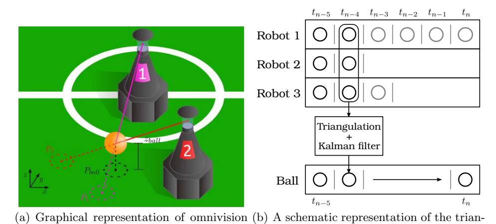
This research has been executed together with the CAMBADA team from Aveiro, Portugal. To detect the position of the ball, most teams have equipped their robots with a (cata-)dioptric vision system [1, 3, 6]. Currently, the ball position is estimated by projecting the ball found in the 2D image on the field in the x − y plane, assuming that the ball is always on the ground when seen by the omnivision. Finding a way to obtain the 3D ball position (xb, yb, zb) enables the robot to follow the correct ball position in x − y plane. Moreover, the height (zb) of the ball serves a purpose by enabling the interception of lob passes [3]. Cooperative sensing can be used to determine the ball position in three dimensions; by triangulation of omnivision camera data. This is graphically represented in Figure 2(a). Here, P1 and P2 are the projected ball positions estimated by respectively robot 1 and 2. Pball is the actual ball position.
Algorithm Structure
A schematic representation of the triangulation algorithm is presented in Figure 2(b). Every execution, the new information from the robot itself and its peers is stored into a buffer, quantized to time instants defined by the executions. The state of the algorithm as presented in Figure 2(b) is at time tn, information from peers is delayed by the robot-robot communication. For triangulation, the algorithm selects a time instant at which information from multiple robots is available. In the case of the state represented in Figure 2(b), tn−4 is selected. The available 2D ball projections at this time instant are triangulated and the obtained 3D ball position is filtered with a Kalman filter, which combines this new measurement with the model of the ball. This yields a (filtered) 3D ball position at time instant tn−4 which is then fast-forwarded in time to tn using the model of the ball.
Results
The algorithm presented in Figure 2(b) has been implemented on the robots of the CAMBADA team. Two kinds of tests have been executed: with a static ball and with a moving ball. Tests with a static ball show that the average accuracy obtained with the algorithm is 10.6 cm, note that the mapping from camera coordinates to robot coordinates has not been calibrated specifically for this test. During the tests with a moving ball an attempt was made to track the position of the ball from the moment it was kicked by a robot (12 m/s). To be able to get a good estimation of the ball position when the ball has exceeded robot height, the state of the Kalman filter has to be converged before this moment. To accommodate this, enough samples from peer robots have to be received. Calculations show that if the robot-robot communication is performed at 40 Hz this is satisfied.
At the moment of writing, the algorithm is also being implemented on the robots of Tech United Eindhoven.
3.2 Integration Kinect v2 camera
For three-dimensional ball recognition, so far we have been using the Microsoft Kinect v1. While this device poses a great addition to the omnivision unit, it also has some drawbacks that makes it unreliable and suboptimal. There are four main shortcomings: i) The CCD has low sensitivity, hence we need to increase the exposure. This causes the Kinect to shoot video at only 15 Hz, instead of the theoretical maximum of 30 Hz. ii) The CCD has bad quality colors, making color thresholding hard, and tuning cumbersome. iii) There are many mechanical problems, causing one of the image streams to drop out, or causing the complete device to crash. And iv) The depth range is limited to 6 m. This means that a full speed ball at 12 m/s arrives 0.5 s after the first possible detection.
A possible solution to the Kinect v1's shortcomings is the Kinect v2 [4]. It has a higher quality CCD with better color quality and improved sensitivity. It is therefore easier to find the ball in the color image, and it can always run at 30 Hz. The depth range has increased to 9 meters, giving the goalkeeper more time to react. Early tests also have not shown any dropouts of the device or its video streams.
For processing the increased amount of data from the Kinect v2, a GPU is required. The current robotic software runs on an industrial computer, which does not have a GPU, nor can it be extended to include one. Therefore, a dedicated GPU development board, the Jetson TK1 [7], is used to process all the data from the Kinect. This board incorporates a 192-core GPU and a quad-core ARM CPU, which is just enough to process everything from one Kinect. The board runs Ubuntu 14.04 with CUDA for easy parallel computation. This enables us to offload some of the graphical operations to the GPU.
First, the video stream data is processed on the GPU. The ball is then detected using the following steps:
- The color image is registered to the depth image, i.e. for each pixel in the depth image, the corresponding pixel in the color image is determined.
- Color segmentation is performed on the color image using a Google annotated database that contains the chance of an RGB value belonging to a color.
- A floodfill algorithm is performed for blob detection (CUDA)
- The blobs are sorted based on their size/distance ratio and width/height ratio:
$$p = \left[1 + \alpha(w - h)^2\right]^{-1} \left[1 + \alpha^2(wh - 4r^2)^2\right]^{-1}$$
with w and h the width and height of the blob respectively, r the radius of the ball and α a scaling factor, all calculated in meters.
- The found balls are transformed into robot coordinates.
The result is an almost 100% detection rate at 30 Hz when the ball is inside the field of view of the camera, and closer than 9 meters.
3.2.1 RTDB multi-network extension
We use the Real-time Database library of CAMBADA (RTDB, [8]) for inter-process as well as interrobot communication. This database is based on records that can be marked either local or shared. A communication process (comm) is running on all robots, which broadcasts the shared records over WIFI using multicast UDP. The same process is also used to receive data to update the local RTDB instance with shared data from peers. This provides a flexible configurable communication architecture for inter-process and inter-robot communication.
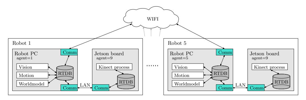
With the introduction of the Jetson TK1 board for image processing of the Kinect v2, the processes on the robot are no longer executed on a single processing unit. As a result, the standard RTDB library can no longer fulfill all inter-process communication on a robot. Therefore RTDB and comm are extended to support multiple networks. The new communication architecture is illustrated in Figure 3. Each robot PC runs two instances of comm. One broadcasts and listens on the wireless interface for inter-robot communication. A second comm instance is connected to a wired LAN interface which is connected to the Jetson board.
Modifications have been made to RTDB and comm to enable this new configuration. First, a network configuration file has been introduced. This file describes for each network the multicast connection properties, the frequency at which comm should share the agents's shared records, and an option to mark the network default to be fully backwards compatible. Two modifications to RTDB have been added to reduce the traffic in the networks. The first one is compression of the data to be sent just before a UDP packet is created. The complete payload of this packet, i.e, data and comm header, is compressed using zlib which reduces the payload on average to about 70% of the original size. Using the second modification, the user can specify in the RTDB configuration file which (shared) records have to be broadcasted in a given network. For example, the Robot PC (agent 1-5), illustrated in Figure 3, is sharing data in two networks. The two networks are configured such that all shared records are broadcasted to all peers through the WIFI network, while only a subset of data is sent to the Jetson board through the LAN network. The Jetson board only needs to know the current robot position and not all team related information. This implementation is also fully backwards compatible; if the network is not specified in the RTDB configuration file, all shared records will be broadcasted.
4 Obstacle detection enhancements
During the past RoboCup tournaments it was observed that the success rate of goal attempts is still too low. For the RoboCup tournament in Hefei 2015 the success rate was somewhere around 20% averaged over all matches according to the logged game data. By improving the obstacle detection the goalkeepers position can be estimated more accurately, which will increase the success rate of shots at goal.
The current obstacle detection method is a relatively simple approach, which uses 200 radial rulers to detect dark objects in the image. The disadvantage of this approach is that the resolution decreases dramatically as a function of distance. Hence, at larger distances only wide obstacles are detected accurately. This results in a 0.25m resolution at an 8m distance. Considering the image resolution, a resolution of 0.03m at 8m distance could be achieved, which is about a factor of 8 better. Hence, the main improvement of the new algorithm focuses on using the available resolution in tangential direction. The new method consists of the following steps:
- Iterate through radii starting from inside outwards;
- Apply an intensity threshold for each circle;
- Apply a circular closing filter to fill small holes;
- Collect candidate obstacles;
- Split obstacles that are too wide;
- Check mandatory features (obstacle is inside field, obstacle large enough in both tangential and radial direction);
- Collect all valid obstacles;
- Update the mask with the found obstacles such that no obstacles can be found behind other obstacles.
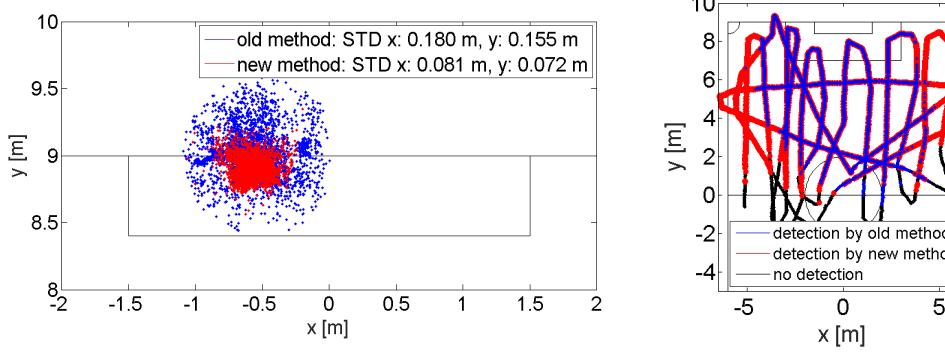
When comparing the old and new method on the robot, the results as shown in Figure 4(a) and 4(b) are obtained. In this experiment, a keeper is positioned at about (−0.5, 9) m pointing forward. The dots in Figure 4(a) illustrate where the obstacle was seen by the robot with the old and new method. It can be seen that the standards deviation is significantly reduced. Figure 4(b) shows that the detection range is also increased. The lines show the trajectory of the moving robot. The color indicates whether the goalkeeper was detected from that position or not. As observed, the new method has an increased detection range.
5 Towards improved lob shots
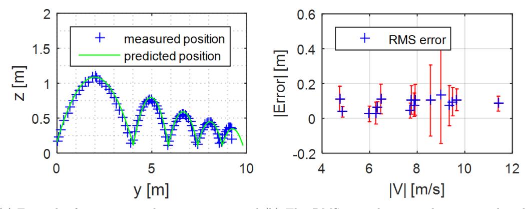
To increase the scoring success rate from lob shots, the accuracy of lob shots is being improved. Therefore the lob shot has been investigated thoroughly. Up to this point a lob ball is given by pulling the ball back as far as possible, setting the shooting lever to its lowest position and determining the kick effort in order to hit a specified target. For each robot the traveled distance of the ball as a function of the kick effort is measured beforehand. This approach of only varying one parameter, i.e. the kick effort, does not make full use of the versatility of the robots and limits the range of accessible targets. To improve the aiming of the lob shots the behavior of a freely moving ball through the air is first investigated and modelled. Next, a model of a bouncing ball, including spin, is made to predict the ball velocity and spin after it hits the ground. Combining both models results in a prediction of the entire path of a bouncing ball. This combined model is tested by tracking a lobbed ball, estimating its initial velocity and spin, and comparing its actual path to the predicted path. One example of this can be seen in Figure 5(a). The distance between the measured position and the predicted position is calculated for the entire trajectory. The root mean square of these distances is taken as a measure for the error between the model and the actual trajectory. In Figure 5(b) this error is shown for several input velocities.
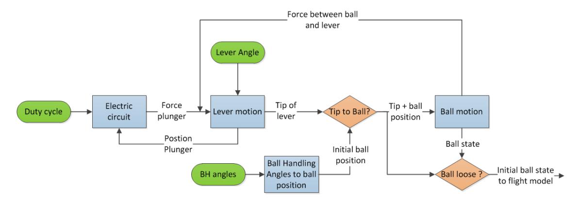
An inverse of this model is made which estimates the initial velocity and spin of the ball in order to hit a specified target. In the software of the robots a desired lever height and PWM (Pulse Width Modulation) dutycycle for the kicker solenoid can be set. In order to use the previously mentioned inverse ball model, a relation between these two inputs and the initial ball velocity needs to be found. Because a capacitor is discharged over the solenoid kicker, the relation between PWM dutycycle and initial ball velocity can in theory described by: $v_0 = \sqrt{\frac{CV_p^2K}{m}}$ where $v_0$ represents the amplitude of the initial ball velocity, C the capacitors capacitance, $V_p$ the capacitor voltage, K the PWM dutycycle and m the mass of the ball. Furthermore, the initial angle of the ball with respect to the ground-plane should correspond to: $\alpha_0 = \tan \frac{R-z}{d-r}$. With R the ball radius, d the horizontal distance between kicker and ball center, z the height of the contact between lever and ball and r the longitudinal distance of the contact point. Several shots with varying inputs were recorded on video and analyzed by software. It appeared that there also exists a cross-relation between lever height and dutycycle settings and resulting ball speed and angle. This probably has to do with the fact that the travel distance of the lever changes according to its height, and thus the amount of energy transferred to the ball, varies with both settings. As a first attempt a two-dimensional second order polynomial was fitted through the experimental data, with inputs K (dutycycle) and L (lever height) and outputs v0 (initial ball speed) and α0 (initial ball angle). This fit was implemented and validated on the robots. First results were very promising, but since the model has quite some parameters (ten), calibrating it on each robot takes a lot of time. Further research should thus be done on simplifying the model and designing smart calibration software. To get a better understanding of the lob shot, a model is made which simulates the entire interaction between the robot and the ball during a shot. In Figure 6 a schematic representation of this interaction can be seen. This model incorporates the dynamics of the shooting system, which combines the electrical circuit to drive the solenoid and the lever that hits the ball. The angles of the ball handling arm effect the position of the ball with respect to the center of the robot. The ball is modelled as a mass spring damper system, which is verified through experiments.
Currently, this model is being tested by shooting a ball with varying inputs and estimating its initial velocity and spin. When the model proves to be correct it can be used and implemented on the robots in order to get a better aiming and more versatility of the lob shot.
6 Visual analysis of logging data
During a match, a lot of data of the robots is shared with peers and the base-station. This data is logged for analysis purposes. Previously the data was mainly used during the match and afterwards for the replay of the game, which gives insight in erroneous and successful events. This year a new visualization tool is developed in cooperation with the visualization research group of the computer science department. The advantages of this new visualization tool are that data characteristics are visible and it allows fast analysis and pattern finding in the data between robots. To accomplish this we used Visual Analytics [2], which combines human qualities such as creativity and background knowledge with the powerful capabilities of a computer to gain new insight into complex problems. A robot soccer team can be seen as a parallel system where multiple agents communicate with each other in order to achieve a common goal. Parallel systems generate large amounts of logging data that can be used to understand and improve their behaviour in an evolutionary way. With this abstract problem in mind a preliminary visualization tool is developed.
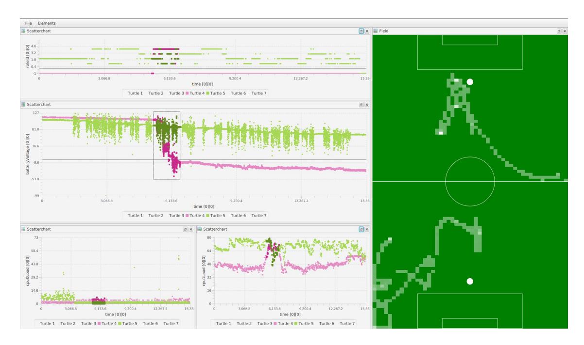
A preliminary version of the new visualization tool is shown in Figure 7. It shows multiple plots and a soccer field which are linked to each other. With these plots robots can be compared. For example, the voltages of two robots are shown in the center plot of Figure 7, it shows that the voltage of TURTLE 4 drained very fast during the game. The visualization tool is very flexible, the x- and y-axis of each plot can be configured with any desired parameter.
7 Conclusions
In our team description paper we have discussed concrete steps towards improved perception using combined omnivision for a more accurate ball position estimation and integrating the Kinect v2 cameras onto the robots. Furthermore, the obstacle detection is improved, now robots have a more accurate obstacle position estimation and obstacles can be detected from a wider range. A new ball model is being developed which takes spin of the ball into account. Finally, we are developing a new visualization tool such that match analysis can be done more effectively during tournaments. Altogether we hope our progress contributes to an even higher level of dynamic an scientifically challenging robot soccer during RoboCup 2016 in Germany. While at the same time maintaining the attractiveness of our competition for a general audience.
References
- Aamir Ahmad, João Xavier, José Santos-Victor, and Pedro Lima. 3D to 2D bijection for spherical objects under equidistant fisheye projection. Computer Vision and Image Understanding, 125:172–183, aug 2014.
- VisMaster Consortium. Visual analytics. http://www.visual-analytics.eu/.
- Tech United Eindhoven. RoboCup 2014: Robot World Cup XVIII, volume 8992 of Lecture Notes in Computer Science. Springer International Publishing, Cham, 2015.
- Microsoft. Kinect v2 technical specifications. https://dev.windows.com/en-us/kinect/hardware.
- Tech United Eindhoven MSL. Tech United Eindhoven Team Description 2014, 2014.
- António J.R. Neves, Armando J. Pinho, Daniel a. Martins, and Bernardo Cunha. An efficient omnidirectional vision system for soccer robots: From calibration to object detection. Mechatronics, 21(2):399–410, march 2011.
- NVidia. Jetson tk1 technical specifications. http://www.nvidia.com/object/jetson-tk1-embedded-devkit.html.
- Almeida L. Santos, F. Facchinetti, T. Pedreiras, P. Silva, and V. Lopes. Coordinating distributed autonomous agents with a real-time database: The CAMBADA project. ISCIS 2004, pages 876 – 886, 2004.