FALCONS Team Description Paper
Jaap Vos
ASML
Abstract FALCONS is a RoboCup team based in Veldhoven in the Netherlands and consists of ASML employees who share the same passion and vision; work with robots as a hobby and become champions at Robocup MSL in the coming years. The Falcons team was formed in November 2013, encouraged and supported by ASML, and today counts about 20 active members. The ASML Falcons team is a voluntary activity outside working hours, sponsored by ASML. The Falcons robocup team share the passion for robotics, technical innovation and teamwork. Together we try to maximize and expand the capabilities of our robots on software, hardware and strategy. Key values for us are: Sharing information, knowledge and having fun. By sharing knowledge we want to push forward the boundaries of the MSL towards the main goal of robocup.
1. Introduction
FALCONS is a RoboCup team based in Veldhoven in the Netherlands and consists of ASML employees who share the same passion and vision; work with robots as a hobby and become champions at Robocup MSL in the coming years.
The Falcons team was formed in November 2013, encouraged and supported by ASML, and today counts about 20 active members.
The ASML Falcons team is a voluntary activity outside working hours, sponsored by ASML.
The Falcons robocup team share the passion for robotics, technical innovation and teamwork. Together we try to maximize and expand the capabilities of our robots on software, hardware and strategy. Key values for us are: Sharing information, knowledge and having fun. By sharing knowledge we want to push forward the boundaries of the MSL towards the main goal of robocup.
Another important aspect of the team is to teach and inspire children for a technical career. To do this, we participate in several events in the Eindhoven area for technical promotion, like the "Dutch Technology Week", presentations and classroom training at secondary schools.
As we aim to teach (technical) skills to children, we also provide opportunities for our members to improve their professional skills. Ranging from deepening the knowledge in their own field of expertise, to learning new technical or soft skills. In this way team members can start new challenges within ASML or practise learnings in their professional or day to day life.
In this document the most significant investigations and improvements for 2018 will be described. Chapter 2 describes the hardware improvements and roadmap including a brief description of the new moving keeper frame. In chapter 3 the new software feature 'Motion Planning' will be explained and the need for a 3rd order setpoint generator will be covered in the final chapter 4.

2. Robot Design Roadmap
The Falcons MSL robots are based on the Turtle 5K design.
Four years ago the Falcons team worked on improving the reliability and predictability of the robots. This phase is successfully finished, playing most games with 5 robots in the field and having a minimum of unexpected behaviour/ rogue robots.
From there the focus shifted to optimizing the software and tactics of the team. Improving the control loops for faster moving and more accurate passing next to better anticipation on the competitor. The FALCONS team has defined a technical roadmap which will constantly enrich the functionality of the existing robots and improve parts which are fully utilized or end of life. The novelty for 2018 will be a mirrorless camera system, with the use of 4 camera's looking forward, each covering 90 degrees. Items on the roadmap are a lighter kicker design, new control electronics, and improved ball handlers.
At the 2017 world championship, the robots were at the maximum weight limit of 40Kg. A weight reduction is needed to enable hardware additions in the future. A weight plan of all components was created and the base plate is changed from steel into aluminium. First steps are taken to redesign the internal structure of the robot and change the shooting mechanism. Together those groups contribute for half the robots weight. The battery packs are now of the NiMh type, for 2019 we want to go to LiPo batteries to allow further weight reduction.

Moving Keeper frame
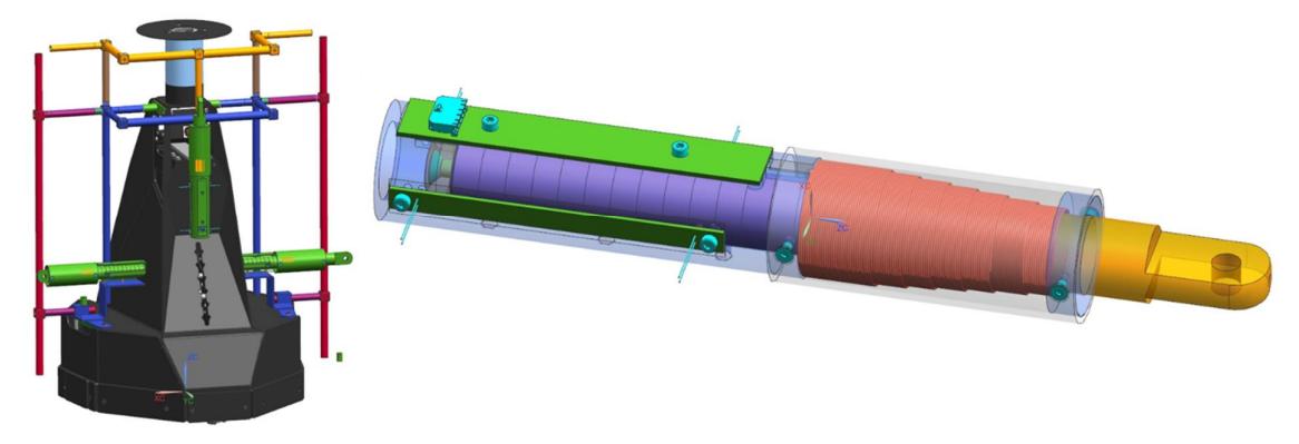
For the Goalie a moving frame is added extend its reach as specified in the rules. The frame will be made of Carbon Fibre for maximum strength and minimal weight. For actuation of the frame an electrical actuator concept is chosen because it is light, robust and fast. With a moving magnet design (and thus a steady coil) routing cables to the moving part of the frame can be avoided making them less prone for damages. In a normal situation the coil holds back the magnet with a hold force. Once the command to extend is given it takes less then 100ms to fully extend. Power is consumed from the 24V batteries. In total 3 actuators are added to the design so the frame can extend in both sides and 1 vertical direction.
3. Software Design
This year the following major (software) changes are introduced:
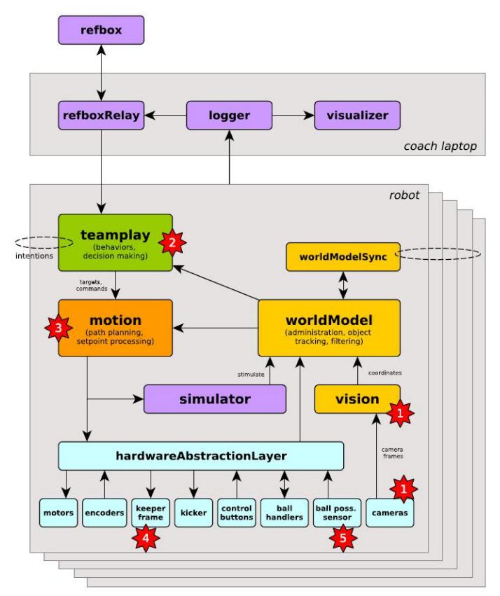
- The omniVision camera module will be replaced by a multiVision 360 degrees module without a mirror.
- In teamplay the concept of heightmaps is introduced, to achieve dynamic positioning.
- In motion, several activities are ongoing to enable faster driving:
- the PID speed setpoint controller is replaced with a setpoint generator. (see Chapter 4)
- a new processing layer 'motionPlanning' is introduced to improve software architecture and increase shoot accuracy (this chapter)
- as motion board replacement the BeagleBoneBlack or similar is under development.
- Moving keeper frame in let right and upwards direction. (see chapter 2)
- As a consequence of the new multiVision system, a new sensor is needed to verify ball possession

MotionPlanning
In the software architecture, the new component "MotionPlanning" was introduced.
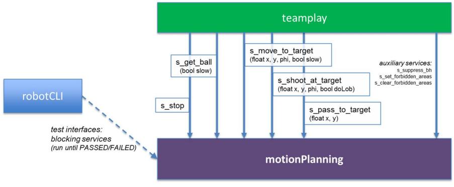
MotionPlanning is responsible for translating high-level Teamplay commands into motion setpoints. This includes sequencing, timing and tolerances. At each software heartbeat, it reports back to Teamplay what the state is of the requested command: passed, running or failed. This then gives Teamplay the choice of continuing with current command, or switching to a different command.
Introduction of this component solves a number of issues:
- wildgrowth: teamplay contained too much motion logic and motion thresholds in its actions layer and even in the behavior trees
- motion logic, thresholds and tricks are now applied in motionPlanning, not in teamplay
- interface spaghetti: teamplay had direct connections with several lower-level motion components, even with hardwareAbstractionLayer
- teamplay now only communicates in a high-level abstraction with motionPlanning, which then will communicate with the lower components (shootPlanning, pathPlanning, etc.)
- poor extendibility: it was relatively hard to apply seemingly simple functional extensions, such as kicker height adjustment during aiming for shot, or sprints for the ball
- these extensions can now simply be introduced in the respective command implementation in motionPlanning
- code duplication in python scripts due to limited test interfaces
- motionPlanning offers straightforward test interface wrappers around the commands it provides to teamplay; these test interfaces block until done and are now called from python test/scripting suite during e.g. technical challenge, or calibration / tuning.
The interface between teamplay and MotionPlanning now is:
As first major functional use case for this component, we improved shoot accuracy while also increasing rotation speed with ball.
The following table shows a collection of problems, causes and solutions we identified and (partially) addressed.
To summarize, our shooting speed and accuracy was improved by
- setting kicker height during rotation,
- waiting for the robot to settle on target, to decouple motion (tuning) issues like overshoot from shoot accuracy,
- using a distance metric instead of a static angle threshold for shoot accuracy,
- increasing rotation speed limit with ball from 1.8rad/s to 3.0rad/s.


Problems, causes and solutions for shooting accuracy
| problem | cause | solution |
|---|---|---|
| too slow | pathplanning tuning | rotate faster: 3 rad/s |
| kick height is set just before shot | set kicker height while rotating | |
| poor shot accuracy | shooting too early (while turning) | settling phase |
| sleep before shot while turning | (+ fallback timeout) | |
| coarse thresholds | tune shot accuracy 5cm | |
| motion not able to reach destination | spg / short-stroke in progress | |
| ballhandling control | increase enable/disable 10Hz $\rightarrow$ 25Hz | |
| add feedforward | ||
| ballhandling calibration | measure more & tuning not planned | |
| vision calibration | calibrate zero x,y,Rz in progress | |
| new camera concept | ||
| lack of diagnostics | ptrace & tracePlot |
4. Setpoint Generator
The ASML Falcons have set the goal to improve the robot's motion for 2018. One of the challenges over the years has been to keep up with the robot speeds of other teams, often resulting in ball loss for the Falcons. Especially in situations where two robots compete to get the ball, the Falcons robot lags behind due to velocity limitations. The idea for 2018 is to achieve higher robot velocities by improving the setpoint computation.

Old situation
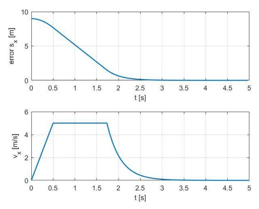
In the old situation the robot's velocity setpoint in , , was calculated from the difference (=error) between current and target robot state. By limiting the velocity ( ) and acceleration ( ) we ensure that the velocity stays within an acceptable range. The problem that comes with this approach is that when the error is large, the velocity setpoint will be large. The opposite holds for small errors between actual and target state: In such a case the setpoint will be low, resulting in (too) slow velocities. Figure 1 visualizes this concept.
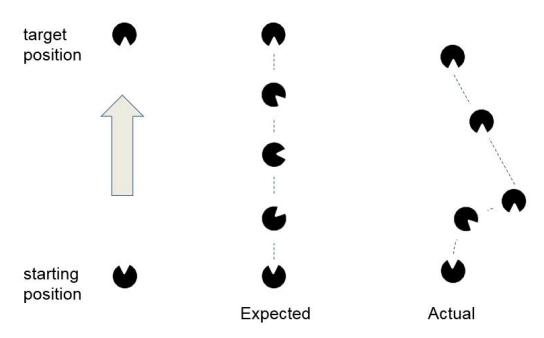
As a result of using this strategy, the robot velocity response is not smooth and too abrupt. The belief exists that this behaviour is causing cross talk between the , and directions, see Figure 2. In order to minimize this effect and avoid collisions, the robot's velocity limit needs to be reduced significantly.
New situation
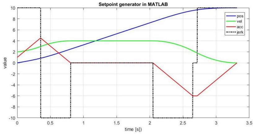
In order to come up with a method to calculate a velocity setpoint that is not suboptimal, we are currently working on the introduction of a setpoint generator. Equation 1 shows the inputs for the setpoint generator: initial position $s_0$ , initial velocity $v_0$ , initial acceleration $a_0$ , target end position $s_{end}$ , target end velocity $v_{end}$ , target end acceleration $a_{end}$ , velocity limit $v_{max}$ , acceleration limit $a_{max}$ , jerk limit $j_{max}$ . The algorithm outputs a third order motion profile for $x, y, \phi$ that, if followed by the motor control, results in a smooth robot velocity profile. An important feature of this setpoint generator is that it can handle an initial speed and initial acceleration that are nonzero. The dynamics of a soccer game can require a robot to update its target position at any given time. In such situations, the setpoint generator must be able to react accordingly and recompute a velocity profile from nonzero conditions. The velocity, acceleration and jerk limit values can be used to tune the setpoint profile, while taking physical limits into account.
$$f(s_0, v_0, a_0, s_{end}, v_{end}, a_{end}, v_{max}, a_{max}, j_{max})$$
Figure 3 shows an example velocity profile created by the setpoint generator.