Water Team Description 2020
Xueyan Wang, Yong Zhao, Song Chen, Xiaoming Liu, Wanjie Zhang, Xinxin Xu, Ye Lyu, Ye Tian, Xinzhe Lyu, Huiyong Zhang, Xinyu Xiao, Chaoyi Chen, Yunxiu Xu
Beijing Information Science & Technology University, NO.12 East qinghexiaoying Rd., Haidian District, Beijing, 100192, China
Abstract This paper describes the Water Middle Size League team for the purpose of qualification to RoboCup 2020. During the last year we made an adaptive image segmentation method based on HSI color space, which can be used for object identification in robot soccer games. This method requires no human intervention, and can guarantee the real-time performance and stability of segmentation to cope with the high real-time requirement and uneven illumination in the competition. Our method is not to focusing on the shape or edge features, but to take advantage of characteristics in histograms in different color spaces to approach segmentation for one frame image. The range value of each pixels in HSI color space is obtained from the segmentation result, then the range value can be used to segment the subsequent images in a high real-time situation. The results shows our method has highly accuracy and stability in most of situations.
1 Introduction
Team Water is a Middle Size League Team of Beijing Information Science & Technology University. The team was founded in 2003.Water has participated in the China Open from 2006 to 2019, World Championships from 2010 to 2019.
World Championships: 1st place: 2010,2011,2013,2015,2017
2nd place:2014,2019 3rd place: 2013,2018
RoboCup China Open: 1st place: 2010,2014,2017,2018,2019
2nd place: 2008,2009,2011,2013,2016
Asia Pacific RobotCup: 1st place: 2019
2 Proposed Method
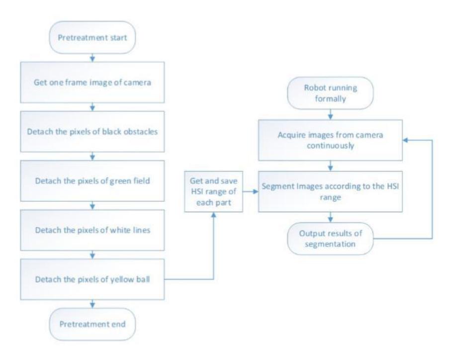
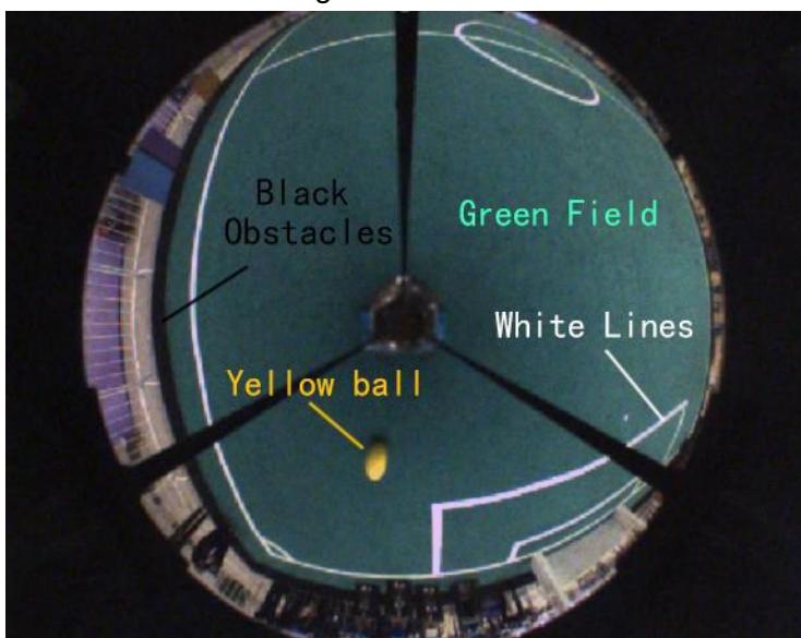
We divide the image segmentation algorithm into two parts. The first part is the preprocessing, which can accurately separate various objects in the image. However, due to the large amount of computation, it cannot adapt to the real-time requirements. The illumination condition will not change much in a short time, so we need to accelerate the image segmentation algorithm. We save the results of preprocessing in the form of HIS range values, and startto segment the images directly through the saved threshold. The processing speed of this process is very fast and can meet the real-time requirements of the algorithm. The algorithm flow chart is shown in figure 2, and the image to be extracted is shown in figure 3.
2.1 Black obstacle extraction algorithm
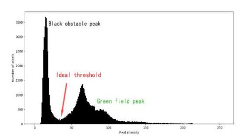
In the rules of RoboCup MSL, The base color of a robot's body must be black. Every team is expected to try hard to hiden on-black parts of the robot as much as possible, especially parts that have colors used for the ball or the field of play[10]Therefore, the black parts in the picture should be regarded as obstacles, the pixel in the black obstacle part of the image is characterized by lower brightness than the pixel in other parts. Therefore, finding a threshold that can separate the black obstacles from the other parts can completes the segmentation. Firstly, the intensity histogram of the image is analyzed and shown in figure 4. According to figure 4, the areas with the largest proportion are black obstacles and green fields. They appear as two peaks in the histogram of figure 4. And the bottom between the two peaks is easy to find, that's the ideal threshold. Due to the fact that there will be no more extreme illumination during the competition, the actual performance of this algorithm is relatively good and is shown in figure 5.
2.2 Green field extraction algorithm
Step1 Filter out the noise
In terms of brightness, the difference between the green field and the non-green are a such as the all, goal and the outside of the field is not very large, but its most obvious feature is its constant hue. However, due to the large a mount of noise generated by the camera, the hue of the noise is quite different from the green field, which will seriously interfere with the identification results. So the filter algorithm should be used to remove the noise in the image. In image segmentation, Preserving the clarity of the boundaries of all parts is of paramount importance, and the Edge Preserving Filter refers to a kind of special Filter that can effectively preserve the Edge information of images in the filtering process, which is very suitable for this kind of scene. Surface Blur is a kind of edge preserving filter[11]Its implementation is relatively simple Surface Blur algorithm is used to filter the image, as shown in equation 1:
$$X_{out} = \frac{\sum_{i=1}^{(2r+1)^2} \left[ \left( 1 - \frac{|x_i - x|}{2.5Y} \right) x_i \right]}{\sum_{i=1}^{(2r+1)^2} \left( 1 - \frac{|x_i - x|}{2.5Y} \right)}$$
Where, r represents the convolution kernel radius, Y represents the threshold value, x represents the current pixel value to be processed, xi represents the ith pixel value in the convolution kernel, and x out represents the output result. The convolution kernel is used for convolution operation, and the filtering effect with clear edges can be obtained. The noise points can be effectively filtered, and the edges can be clearer, so that the algorithm can correctly segment the image.
Step2 Obtaining and smoothing of hue histogram
In HSI color space, The hue value of the green field is more prominent, Therefore, we conduct histogram analysis of filtered image. Firstly, the image is transformed into HSI color space and the hue values of all pixels are extracted and the histogram of the hue values is drawn as Green Hue Hist.
Due to the largest number of green pixels, there will be an obvious peak in the histogram. As long as the boundary value of this peak can be extracted, the green field can be separated. But the boundary value of this peak is fuzzy and difficult to determine. So the histogram smoothing method is used to smooth the histogram. Interpolation based histogram smoothing method can quickly combine the histogram peaks and the surrounding complex signals into wave peaks with obvious single boundary. The interpolation - based histogram smoothing method is calculated by equation2 : .
$$temp = \frac{1}{step} \sum_{i=-\frac{step}{2}}^{\frac{step}{2}} f(x+i)$$
Step3 Histogram peak boundary acquisition
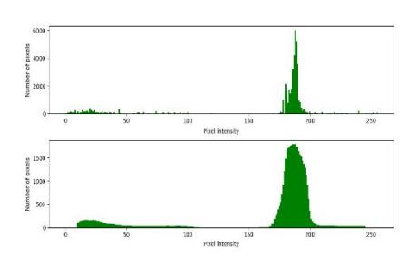
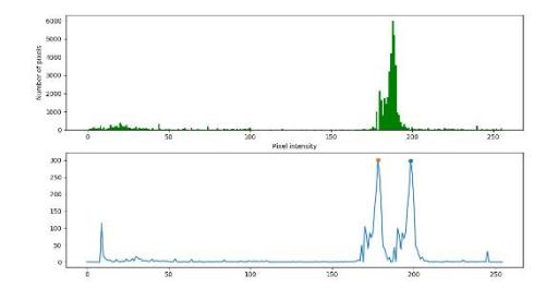
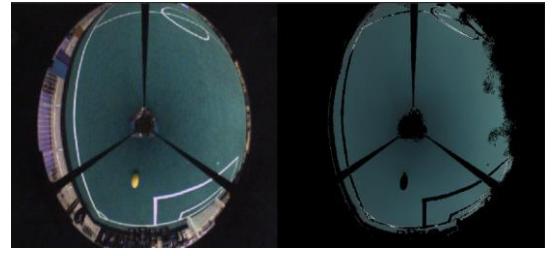
After obtaining the smooth hue histogram, the peaks of the more obvious green parts are obtained. The first order differential of Green Hue Smooth is carried out to obtain the histogram change rate function. The two highest points of this function are the boundary of the peak. Take the boundary of two peaks as the range value of hue, filter all pixels, the segmentation image of the green field can be obtained. The results of histogram smoothing and derivative peak are shown in figure 7 and 8, and the ultimate extraction results are shown in figure 9.
2.3 White field line extraction algorithm
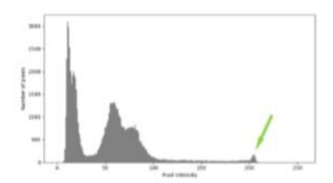
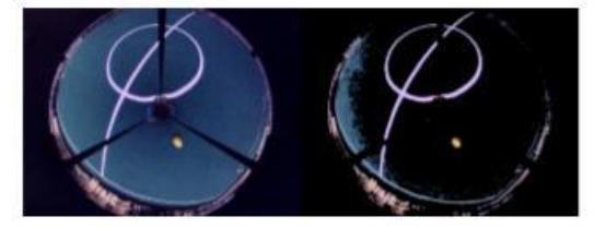
The accuracy of robot self-positioning depends most on the white field line, so the recognition effect of the white field line is very important. Similar to the black obstacles, white field lines have extreme values in intensity. In the intensity histogram, the pixels of the white field line creates a higher peak on the right side of the histogram. This peak concentrates most of the pixels of the white field lines. Most white field lines can be extracted from this way, as shown in figure 10.
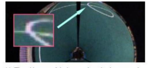
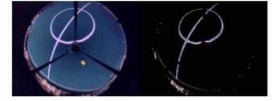
However, due to the dispersion of the lens, the setting of white balance and other issues, the brightness and color of the white field line pixel are not uniform, and other colors different from white also appear, as shown infigure11.Butwhatthesewhitefield lines have in common is that they have higher intensity and lower saturation. So we can separate it from the rest based on the properties. On the left side of the white line peak on the right in figure 10, there is a long section of relativelyflatpart, where the field line with low brightness at the edge of the lens and other pixels with high brightness, such as the ball and the interference outside the field are inside. Therefore, the following steps are proposed to extract white field lines: Step 1The peaks distributed to the right of intensity histogram and the pixels in the flat area to the left are extracted, as shown in figure 12. Step2Get the saturation of the white field line from the pixel in the right peak. Step 3 Filter the pixels extracted in the first step again with the saturation obtained in the step 2, as shown in figure 13.
2.4 Extraction of yellow ball
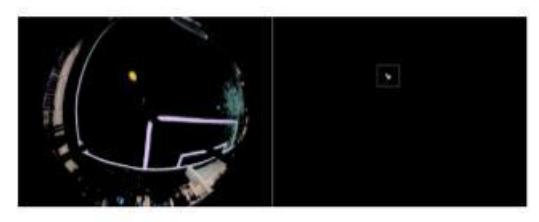
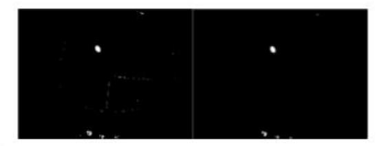
In the MSL RoboCup competition, a full-size soccer ball is required, but the soccer ball is painted yellow. In the competition field, the brightness and saturation of the yellow ball are high, and the ball can be separated according to these two characteristics. It can be seen from figure 12 and 14. In the first step of white line extraction, the yellow ball is also extracted. Because the ball has a higher brightness, it can continue to extract the ball based on the high saturation of the ball. The following methods are proposed: . Step 1
It is processed in the result of the first step of white line extraction, converted to HSI color space, filtered with saturation range [a, Max], and reserve only the pixels in this range. a began to decrease gradually from Max and used morphological filtering to filter out noise points, as shown in figure 16. The initial saturation range is narrow, so few pixels are filtered out and the result is all black. Continue to reduce the a until the first valid block (number of pixels greater than a certain value) appears in the result. Record the center coordinates of this pixel block, as shown in figure 14. Step 2
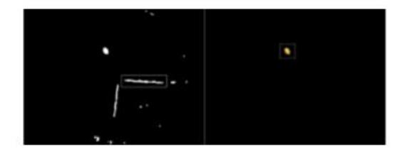
Continue the process of the first step, and use the contour detection algorithm to find the center of the pixel block with the largest area in each obtained result. When the center is not included in the pixel block of the first step, the iteration stops. The result is shown on the left of figure 15.
Step3
When the iteration stops, only the pixel block where the center coordinate of the pixel block recorded in the first step is kept, and the pixel where the ball is can be obtained by clearing all other parts of the image. The result is shown on the right of figure 15.
2.5 Acceleration of image segmentation algorithm
Through the process above, the function of automatic image segmentation is realized. However, the processing time of the above algorithm is relatively long. In the competition, the robot moves at a fast speed and its limit speed is close to 5m/s, so the speed of image processing is extremely high, and the processing speed should reach more than 30fps.The processing speed of the above algorithm is lower than 1 Fps, so a faster image segmentation method should be used on the basis of the above algorithm.
Step1
The images of the four parts separated by the above algorithm are converted into HSI color space, and all pixels are traversed to obtain the upper and lower limits of H, S and I values respectively.
Step2
Modify some of the values in the result obtained in the first step. The hue of the black obstacles and the white field line are meaningless, so regardless of the results obtained in the first step, they are modified to the lowest and highest values (usually [0,255]). The white field line is usually the brightest part of the image, so change the upper limit of its brightness value to the highest (usually 255).Save all threshold results. Step 3
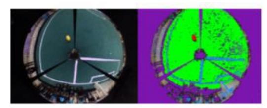
For later camera input images, there is no need to go through the first and second steps of the process. Traverse the whole image, and then filter according to the ranges saved in the second part to get the segmentation result of the four parts. After running the previous work of the first step and the second step, the subsequent image segmentation only needs to continue to execute the process of the third step and only need to traverse the image once to complete the image segmentation. We represent the segmented results in different colors for easy observation. Black obstacles are represented by purple, green fields are represented by green, white field lines are represented by blue, and yellow balls are represented by red. The visualization is shown in figure 17.
3 Experimental results
In order to evaluate our proposed algorithm, we use two evaluation methods to determine the results of image segmentation. First method is to determine whether the robot can correctly complete the movements of moving, avoiding obstacles and catching balls. The second method is to compare the pixels in the results of each part with ground-truth to get the accuracy. The judging criteria are shown in equation (3).
$$Accuarcy = \frac{PixT - PixF}{PixG} \times 100%$$
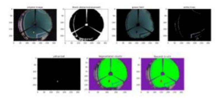
Let see about the Experimental results of a common situation in figure 18.
4 Conclusions
This paper describes our team make a research about adaptive robot soccer image segmentation based on HSI color space and histogram analysis during the last year. According to the paper we solved the problem that we have a lot time to mark the color in the field. Save a lot of time in debugging.
References
[1] H. Kitano, M. Asada, Y. Kuniyoshi, I. Noda, and E. Osawa, Robocup:The robot world cup initiative, in Proceedings of the first internationalconferenceonAutonomousagents,pp.340-347,ACM, 1997. [2] H. Kitano, M. Asada, Y. Kuniyoshi, I. Noda, E. Osawa, and H. Matsubara.Robocup:Achallengeproblemforai,AImagazine,vol. 18, no. 1, p. 73, 1997. [3] HOME OF THE MSL, https://msl.robocup.org 2019 [4] Liu Fei, Lu Hui-min, Zheng Zhi-qiang.A modified color lookuptablesegmentationmethodforrobotsoccer[c]//4thLatinAmercia Robotic Symposium/IX Congreso Mexicano de Robotica 2007(4th) IEEE LARS/COMRob07), Monterry, Mexico, 2007 [5] A. N. Fitriana, K. Mutijarsa, W. Adiprawita.Color-Based Segmentation and Feature Detection for Ball and Goal Post on Mobile Soccer Robot Game Field[J].2016 International Conference on Information Technology Systems and Innovation (ICITSI),2016,ISBN: 978-1-5090-2449-0. [6] Yongbo Qian and Daniel D. Lee.Adaptive Field Detection and Localization in Robot Soccer[J].20th RoboCup International Symposium, Leipzig, Germany,2016. [7] Härtl A, Visser U, Röfer T. Robust and efficient object recognition for a humanoid soccer robot[C]//Robot Soccer World Cup. Springer, Berlin, Heidelberg, 2013: 396-407. [8] Bailey D, Contreras M, Gupta G S. Towards automatic colour segmentationforrobotsoccer[C]//20156thInternationalConference on Automation, Robotics and Applications (ICARA). IEEE, 2015: 478-483. [9] Speck D, Barros P, Weber C, et al. Ball localization for robocup soccer using convolutional neural networks[C]//Robot World Cup. Springer, Cham, 2016. [10] MSL Technical Committee.Middle Size Robot League Rules and Regulations for 2019.