Hibikino-Musashi Team Description Paper 2022
Moeko Tominaga, Yasunori Takemura, Kazuo Ishii
Nishinippon Institute of Technology, Japan; Kyushu Institute of Technology, Japan
Abstract In this paper, we present some of the technical characteristics of the "Musashi robot", developed for the RoboCup Middle-Sze League. We focus on our original developments and research studies, which contribute improving the Middle-Size League, neglecting those characteristics that are common to many other teams. In particular, we describe three main results of our team. The first result regards the active handling ball system, by which the robot keeps the ball using a mechanism driven by two motors. The second result regards the obstacle avoidance algorithm, which is based on Dynamic Window Approach. Finally, we describe our ball passing algorithm, based on probabilistic robotics. These results increased the performance of our multi agent system, enhancing the cooperation among the robots.
1 Introduction
"Hibikino-Musashi" is a joint middle-size league RoboCup [1] [2] soccer team founded in 2004 by three different research and educational organizations, all located in the Kitakyushu Science and Research Park, in Kitakyushu, Japan. The team's main objective is to create innovative technology for human society by developing a competitive team of soccer-playing robots. The research carried out on our robots allow us to implement some innovative technologies and solutions on real life problems. For example, inspired by our robots, we developed an Omni-wheeled wheelchair.
In this paper, we describe our most recent developments. In section 2, a short overview to the "Musashi-150" robot design principles and its modular hardware architecture is presented. The concept and specification of our new ball handling mechanism is described in Section 3. Section 4 and 5 describe our software developments. In particular, in section 4, obstacle avoiding algorithm considering robot dynamics is proposed and tested in simulation. Section 5 describes that ball passing behavior based on probability map from teammates and opponents.
2 Hardware System
Section placeholder
2.1 Musashi150 Robot Architecture and Specification
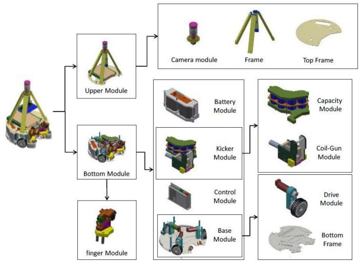
The current hardware configuration of the "Musashi 150" robot, with its fully modular mechatronics architecture, is shown in Fig. 1. This includes an Omni-directional moving mechanism and an Omni-vision system. The modular robot architecture provides an effective way to improve reliability, robustness, ease of maintenance and transportation, by decomposing hardware complexity into the smaller and compact modules. The robot is equipped with three 150 watts DC motor from Maxon, arranged in the shape of Triangle.
The maximum nominal motor speed of 7580 rpm is decelerated through a planetary gearbox GP42 with a ratio of 6:1, and further decelerated through a belt and pulley system, with a ratio of 2:1. The amplified mechanical torque on the output pulley is trans-ferred to the wheel's shaft through supported by a pair of the radial ball bearings. The velocity feedback is obtained by using 2000 pulses digital incremental encoders. The velocity of the wheels is controlled by three EPOS motor drivers from Maxon. Each component is connected through Controller Area Network(CAN). The controllers read the pulse trains from the motor encoders and produce PWM output voltages for the motors based on a PID algorithm. The result is a maximum linear velocity of 3.5m/s and acceleration of 2.1 m/s2 . The sensors used in the "Musashi150" are an Omni-directional camera, a compass, and three DC motor encoders. The electrical power is supplied by a set of Nickel - Hydrogen batteries (nominal voltage 24V/2.8Ah). The necessary voltage for the camera, compass module and the microcomputer are obtained by converting 24V to 12.0V and 5.0V. To realize the shooting function for kicking the ball, an electromagnetic kicker is designed and constructed specifically for "Musashi150". The kicker is based on an Induction -Coil- Gun Approach, and it consists of two interacting parts, the coil and the rod. Finally, "Active-Fingers" equipped with small wheels are used to control the ball.
3 Active Ball Handling Mechanism
A previous version of our robot, the "Musashi", that was developed in 2005, had a ball handling mechanism consisting of a cam that can rotate and close the arm to keep the ball. This system wasn't able to keep the ball stable in case of quick movements, such as a sudden stop. Moreover, in 2012 a new rule required the robots to pass the ball to teammates during the game, which made the importance of a good ball handling system even more critical. Therefore, we implemented the new Ball Handling Mechanism for improving the robot capability to keep the ball. The new mechanism is shown in Fig. 4 and Fig. 5. When the robot catches the ball, the wheel starts spinning, driven by the pulley connected to the motor. The required rotational velocity of the wheel is calculated based on the moving direction and the velocity of the robot, and it allows to hold a ball while turning. In addition, an Omni wheel was attached at the bottom of the handling mechanism, to improve the grasping stability while the robot is dribbling. The specifications of the Ball Handling Mechanism are shown in Table 1.
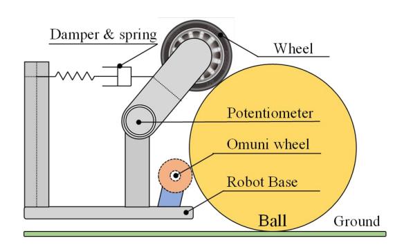
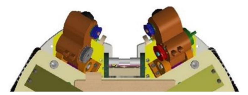
Table 1. Specification of Ball Handling Mechanism
| Voltage | 24[V] |
|---|---|
| Maximum Power | 50[W] |
| Maximum Motor Speed | 13100[rpm] |
| Maximum Motor Torque | 48.2[mNm] |
| Wheel Size | 60[mm] |
| Reduction Rate | 10.56 |
4 Obstacle Avoidance
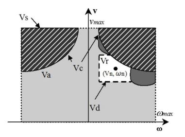
Obstacle avoiding capability is an essential skill in RoboCup, since it permits the robot to move safely during the match, without collisions with other robots or with the fences of the field. Obstacle avoiding skill requires path planning and dynamic control. Accordingly, we developed a new obstacle avoiding algorithm based on Dynamic Window Approach (DWA) [3]. DWA is well-known obstacle avoiding algorithm that generates dynamic-safety path considering the maximum velocity and acceleration of the robot. However, this algorithm does not consider the centrifugal force. This causes side slip in vehicles such as Omni-wheeled robot. We included the centrifugal force into the DWA, and achieved a safe movement of the robot. The proposed algorithm consists of 2 steps. In the first step it is defined the robot velocity space that can be achieved in next control cycle, Fig. 6. In the second step an imaginary path is generated and evaluated by using an evaluation function, which considers safety and rapidity. The robot velocity space in next control cycle is restricted by dynamic and kinematic limitation. First limitation is maximum velocity, whose area is named $V_s$ in Figure 6. Second limitation is maximum acceleration, whose area is named V. in Figure 6. This is calculated by Equation (1). Where vn and $\omega n$ are the robot translational velocity and angular velocity respectively; $\alpha$ max and $\omega$ max are the robot maximum acceleration and angular acceleration respectively; dt is control cycle of robot.
$$V_{d} = \begin{cases} (v_{n} - a_{max})dt \le v \le (v_{n} + a_{max})dt \ (\omega_{n} - \dot{\omega}{max})dt \le \omega \le (\omega{n} + \omega_{max})dt \end{cases}$$ (1)
Third limitation is represented by the obstacles, $V_a$ in Figure 6. This is calculated by Equation (2). Where ld is the distance between the robot and the obstacle, in the calculated path.
$$V_{a} = \begin{cases} v \leq \sqrt{2 \cdot l_{d} \cdot a_{max}} \ \omega \leq \sqrt{2 \cdot l_{d} \cdot \dot{\omega}_{max}} \end{cases}$$ (2)
Fourth limitation is the centrifugal force, ( in Figure 6. Robot centrifugal force is calculated by using Equation (3). Where m is the mass of robot. We assume the value of centrifugal force at which the robot starts to skid. Finally, the velocity space is calculated by the intersection of each space.
$$V_r = V_s \cap V_d \cap V_a \cap V_c \tag{3}$$
Then, a pair of velocities is selected. The imaginary path is generated from these velocities, and the path is calculated. The length of the path is calculated by Equation (4).
$$l = \frac{v_n}{2 \cdot a_{max}} \tag{4}$$
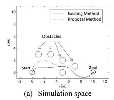
After generating the imaginary path, this is evaluated by using the evaluation function. Some evaluation functions were proposed in [3] [4] [5]. We applied the evaluation function proposed in [5] to our system. We verified the effectiveness of the proposed method by simulating it. Robots are run in simulation space that contains obstacles by using original DWA and the proposed method. Trajectories and centrifugal forces are measured during the simulation. Simulation results are shown in Figure 7. The comparison between the proposed method and the existing methods, to reach the goal is shown in Figure 7(a). Figure 7(b) shows the history of centrifugal forces on each trajectory. A huge centrifugal force was exerted in the range of 0 to 2 seconds, when original DWA is used. Such a huge value did not appear with the proposed method. Therefore, the proposed method achieves more safe movement than the original DWA.
5 Ball Passing Behavior Algorithm
The robots' ability to pass the ball represents an essential skill in a RoboCup match. To realize the passing behavior among robots, it is necessary to recognize the place where it is easy to receive the ball passed from a teammate. This place is determined from the disposition of the robots of both the teams. Probabilistic robotics is a field aimed to take into account the uncertainty of a dynamic environment [7] [8]. To decide point where to pass the ball, a selection map is created by using the normal distribution function. The location where the pass is likely to succeed is calculated by the pass point selection map [9]. The normal distribution is a distribution with a probability density function as in Equation (5) [10].
$$f(x) = \frac{1}{\sqrt{2\pi\sigma}} exp\left(-\frac{(x-\mu)^2}{2\sigma^2}\right)$$ (5)
x: The probability variable,
$\mu$ : The average of the normal distribution,
$\sigma$ 2: The variance of normal distribution,
$\sigma$ : The standard deviation of the normal distribution
The normal distribution of Equation (5) assumes that x is a scalar value. Often, x will be a multi-dimensional vector. Normal distributions over vectors are called multivariate. The multivariate normal distribution is a distribution with a probability density function as in Equation (6).
$$f(x,y) = \prod_{k=x,y} \frac{1}{\sqrt{2\pi\sigma}} \exp\left(-\frac{(k-\mu_k)^2}{2\sigma^2}\right)$$ (6)
$\mu k$ : The average in the probability variable x, y,
k: The probability variable x, y
5.1 Pass Point Select Algorithm
The pass point selection map is created by combination of five conditions [11], which are described below.
Condition no.1: Passing range of the passer robot.
Condition no.2: Receiving range of the receiver robot.
Condition no.3: Range of opponent robot intercept pass.
Condition no.4: Select the robot closer to the goal.
Condition no.5: Pass impossible range of opponent robot backward.
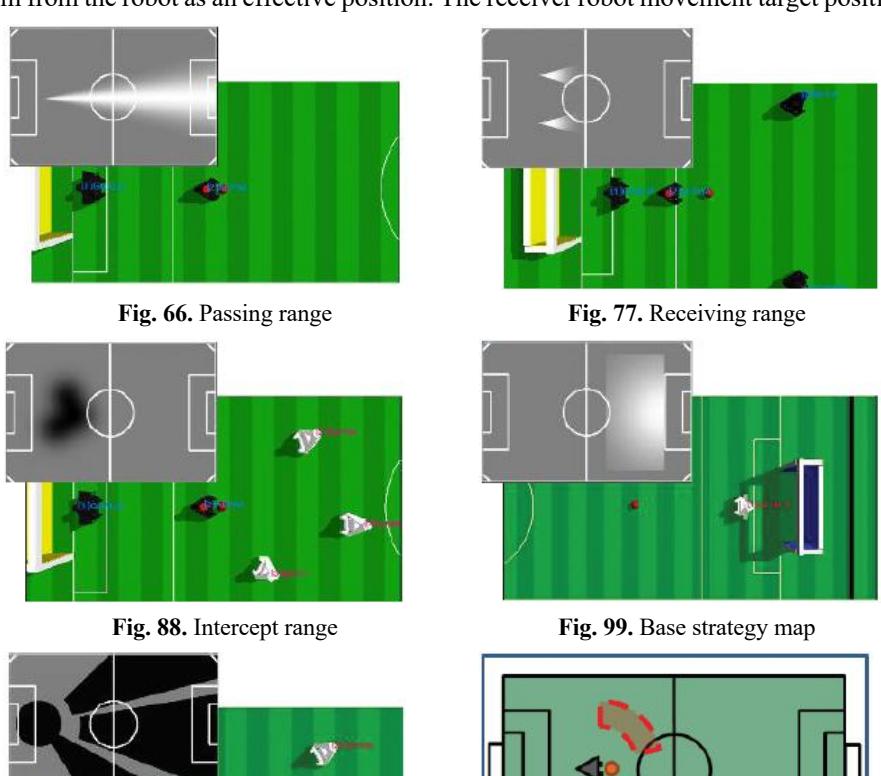
The conditions from 1, 2, and 3 define the pass success probability corresponding to each robot position. The condition 4 and 5 define the pass behavioral conditions related to the strategy. The pass point selection map is formed by adding the respective maps of each condition from no.1 to no.5. Finally, the target pass point is calculated from this map. The maps of each condition are shown from Fig. 6 to Fig. 11. The simulation figure of MSL is shown on the right side of the figures from Fig. 6 to Fig. 11. In the simulation figure, the black objects are opponent robots and the white objects are teammate robots. The figure of the pass point selection map is in gray scale. If the calculation value is 0, black points are plotted on the figure. If the calculation value is 255 of maximum, white points are plotted on the figure. So, the point where a pass has the higher probability to succeed is white. The highest point in the pass point selection map is a target point.
5.2 Receive Point Select Algorithm
The point where the robot is likely to receive a pass is defined in the map shown in Figure 11. A good position to receive a pass is around the passer robot. However, a position too close to passer robot is not effective as strategy. Thus, we set a radius of 3m from the robot as an effective position. The receiver robot movement target position selection map is shown in Figure 13. This is formed by adding the respective maps of condition no.3 and no.5.
In this study, we have accelerated and improved the algorithm of passing behavior by soccer robots. By improving the algorithm, we succeeded in reducing the computational time required for the pass point selection map.
By improving the algorithm, we succeeded in reducing the computational cost of the time required for the path selection map. By speeding up the behavioral algorithm of the soccer robot, it is possible to select a path point and perform a passing action even in a real environment, without compromising the robot's motion performance. By treating the surrounding objects probabilistically, the robot can select a path point while considering the next state even in a dynamic environment. By improving the receiver's behavioral algorithm, we performed path behavior in a real environment. By having the receiver robot move around the passer at all times, the receiver robot can immediately perform the passing action in any situation. In addition, we confirmed that the receiver robot can select a passing point and perform the passing behavior in the real game environment.
References
- H.Matsubara, M.Asada, H.Kitano, "History of RoboCup and Prospects of RoboCup -2002", RSJ, Vol.20, No.1, pp.2~6, 2002, In Japanese.
- Amir A.F. Nassiraei et al., "Hibikino-Musashi Team Description Paper", RoboCup, 2011.
- D. Fox, W. Burgard, and S. Thrun, "The dynamic window approach to collision avoidance," IEEE Robot. Autom. …, pp. 1-23, 1997.
- O. Brock and O. Khatib, "High-speed navigation using the global dynamic window approach," Robot. Autom. 1999. …, 1999.
- B. P. G. K. Konolige, "Planning and Control in Unstructured Terrain," 2008.
- Masafumi Kuwada, " Ball passing behavior for middle sized RoboCup soccer Robots : High speeding technique of path point selection algorithm", The Proceedings of JSME annual Conference on Robotics and Mechatronics (Robomec), June(2015), pp. 2A1-N10(1)-_2A1- N10(3).
- R.Ueda, "Prospects of probability robotics", Journal of Robotics Society of Japan, vol.29, No.5, pp404-407, 2011
- Y.Matsumoto, "Robotics application of probability theory", Journal of Robotics Society of Japan, vol.29, No.5, p403, 2011
- Kazunori Fujimoto, "Development of pass behavior algorithm in the plurality autonomous mobile robots", Kyushu Institute of Tech., Master's thesis, 2011
- Sebastian Thrun, Wolfram Burgard, Dieter Fox,"Probabilistic ROBOTICS", The MIT Press, pp14-15, 2005
- Yutaro Ono, "Ball passing behavior for middle sized RoboCup soccer Robots", Kyushu Institute of Tech., Master's thesis, 2013