Falcons Team Description Paper 2020
Stan Mertens, Erik Kouters, Jan Feitsma, Ronald van der Weide
Falcons, Veldhoven, The Netherlands
Abstract The Falcons are a robotic soccer team participating in the RoboCup Middle Size League (MSL). Over the course of the last year, several significant improvements and investigations have been performed. This paper describes the most notable developments done in order to qualify for RoboCup 2020. These developments include the design of a new hardware platform and introduction of Blockly.
1 Introduction
The Falcons are a robotic soccer team from Veldhoven, The Netherlands, who participate in the RoboCup MSL. The team consists of around 40 ASML employees who share the same passion and vision: to work with robots as a hobby and become champions in the RoboCup MSL league in the foreseeable future.
The Falcons team is a voluntary activity outside working hours, actively encouraged and supported by ASML. We share a passion for robotics, technical innovation and teamwork. Together we try to maximize and expand the capabilities of our robots on software, hardware and strategy. Key values for us are: sharing information, knowledge and having fun. By sharing knowledge, we want to push forward the boundaries of the MSL towards the main goal of Robocup.
An important aspect of the team is to enable, train and inspire people. For example we try to inspire children and students for a technical career. To enable this, the Falcons implemented Google's Blockly as an easy way to control the robots and execute small assignments. Another example is that our team members have opportunities to improve their professional skills. This can range from deepening the knowledge in their own field of expertise, to learning hard or soft skills. In this way, team members can prepare themselves for new challenges within ASML, and/or practice learnings in their professional or day to day life.
This paper gives a brief overview of the status of our soccer robots and describes the most significant investigations and improvements for 2020. In section 2, an update on the development of a new hardware platform is given. Section 3 presents the introduction of Blockly. The ongoing effort to improve the robot software is described in section 4, while section 5 elaborates on the design changes of the electronics architecture.
2 Robot hardware platform update
In 2018 an update of the mechanical platform was introduced to implement the new motion control system. The results were not as expected. Therefor the decision was made to design a new platform to enable better performance, increase serviceability and decrease vibrations.
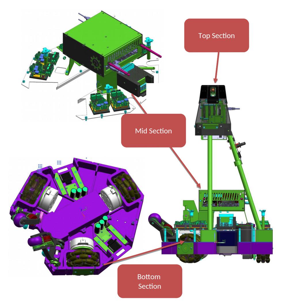
The robot has three sections. The bottom section is made from milled aluminum with minimal openings on the bottom side. Also support beams are added to the frame to increase the stiffness of the frame. This section includes the motors, batteries and shooting mechanism. The top side is covered by an aluminum plate to increase the frame's stiffness further.
Three 3D printed blocks are used as an interface between the bottom and middle section and will also clamp the carbon fiber rods for the top module. The middle section contains the electrical boards, such as motor drivers and power distribution. The CPU box is lowered and mounted in the center of the robot.
The four carbon fiber rods will hold the mirror-less camera assembly and will also hold panels with RGB LED's. Transparent covers of the LED's will contain the robot identification number, while the RGB LED's will provide background lighting in the team color.
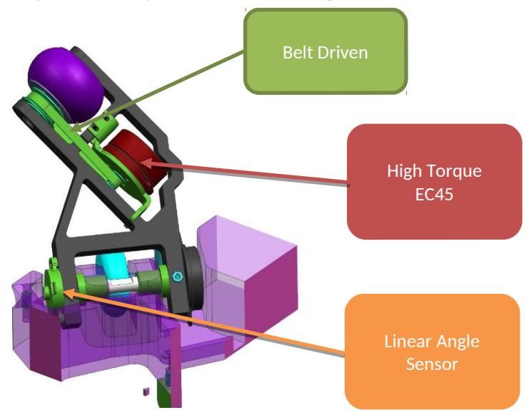
Better performance is achieved by using direct drive motors that have more torque, less lead time and are cheaper than the previous used motors. The diameter of the motors increase and to compensate for this, the Omni wheels also have a larger diameter. These have also three disks with rounded rollers to increase the traction and reduce vibrations. In the ball handling also different motors are used for the same reasons as the drive motors. The change in diameter for the wheels and motors increased the ground clearance. The control architecture has also changed, but will be explained in more detail in part 6.
Besides the different motors, more changes are made to the ball handling system. The angle sensor has been replaced by a linear sensor, the metal bar in front of the wheel is removed and shock absorbers are added. With these changes, the ball handling performance is expected to increase.
The current robots are reliable, but when they break down, it can be hard to access the parts. In the new design, all replaceable part in the bottom frame are mounted from the bottom side. The middle section is easily accessible from the top and all cables that are not routed on this plate have connectors, for easy removal in case the middle section needs to be removed.
Drawing of the new design are on the next page. One important side note in this section is that at the time of writing this paper, the design is being finalized. It's not guaranteed that the robots described here will compete at Robocup 2020 in Bordeaux. If testing shows problems, the current robots will be used. A full explanation is in the Team description papers of 2018[ CITATION Jaa20 \l 1043 ] and 2019[CITATION Edw19 \l 1043 ].
3 Introduction of Blockly
The Falcons Soccer Robot's software is growing more complex each year, which makes it more difficult for new team members to familiarize themselves with the system. Moreover, with this increasing complexity of the software architecture, it was becoming increasingly difficult to test subsystems of the Soccer Robot. To abstract this complexity, we decided to go for a more graphical approach.
A graphical approach allows us to abstract the Soccer Robot's software at different levels. As of now, we have chosen for two levels of abstraction. One level of abstrac tion is close to the software, which lends itself for quickly testing specific subsystems of the software architecture. The second level of abstraction is a highly simplified version of controlling the software.
Inspired by VDL RobotSports, whom use Snap! to control their robots for technology promotional use, we decided to use Google Blockly. Google Blockly is a JavaScript library for building visual programming editors, which allows us to define our own blocks to control the Soccer Robot with.
3.1 Advanced abstraction level
The Advanced abstraction level is used to test subsystems of the software architecture. It allows any team member of the Falcons to quickly stimulate any subsystem they want, without investing much effort of putting the Soccer Robot in a specific 'testing state'.
For example, when the Goalkeeper is serviced by the Hardware team, and they want to test the Goalkeeper extensions, they can simply open up a web browser and drag and drop the 'Goalkeeper extend LEFT' block.
3.2 Simple abstraction level
The Simple abstraction level allows anyone without knowledge about the Soccer Robot to control it. The main purpose of this abstraction level is to allow the Falcons Demo team to make students enthusiastic about technology at Middle Schools and High Schools.
4 Software improvements
As the software team had a lot of new members, time was divided between getting them up to speed and continue improvements on the software. Obstacle tracking is improved to be more accurate for maneuvering in between opponents. One of the improvement is preventing multiple obstacles to merge into one big obstacle. It happened that when more robots were close to each other, or the black boundary was behind the robot, they merged into one obstacle and the robots didn't make optimal tactical decisions. More important, the robots are able to move through smaller gaps in the opposite defense.
Another improvements is the ball tracking accuracy. In games it happened regularly that the goalkeeper moved to the wrong corner, based on incorrect data from a field player. In some cases the goalkeeper was too far off, to catch the ball in the end. An extension of the ball tracking is the improvements of the keeper extension reaction. When a ball come towards the keeper at slower speed, the keeper extension reacted before the ball was in reach. When the ball was at the keeper, the extension was already redrawn.
With the work on the new hardware platform ongoing, also the work on the motion control system continued. Much effort was put into getting the kernel and library's running on the beaglebone black and establishing stable communication with the motor controllers. When this is done, the current control algorithms will be ported to the new platform and the robots will be tuned again, due to the new traction and weight distribution. From there on, new improvements of the motion control and ball handling control will be implemented.
A few years ago, the tactical play was very simple, if allowed to shoot at goal, shoot at goal. This was then improved to include lob shots when opponents were in the path between robot and the goal. This year, the next step is implemented in enabling the robot to move with the ball towards a better shooting position, when for example the opponent keeper is in the way. Also the option to pass towards another player is enabled.
To do this in a good way, better ball handling is needed then shown the last years. The new platform is designed to make it possible. However, there is a chance it's not ready in time or performs not as expected, the tuning of the current robots is further optimized. Strafing with the ball is now possible and makes the robots more maneuverable, especially in areas with multiple opponents.
Last but not least, in vision this year is spend mostly on the ground work for an overhaul of the current algorithm. This is still in an early stage of development and is not expected to be used in Bordeaux. But also here, some better tuning and adjustments increased the accuracy of the data provided to world model and thus enabling the improvements in ball and obstacle tracking described above.
5 Electronic design update
A beaglebone black is used as a local controller for controlling the drive motors and ball handling motors. The processing power of the controller will receive velocity setpoints from the CPU and feedback from the motor drivers. These are used to calculate the new setpoints for each motor. By using EtherCat protocols, the control loop is increased from 100Hz to 1000Hz. The beaglebone black is also used to control the shooting mechanism and identification colors and can read sensor and diagnostic signals.
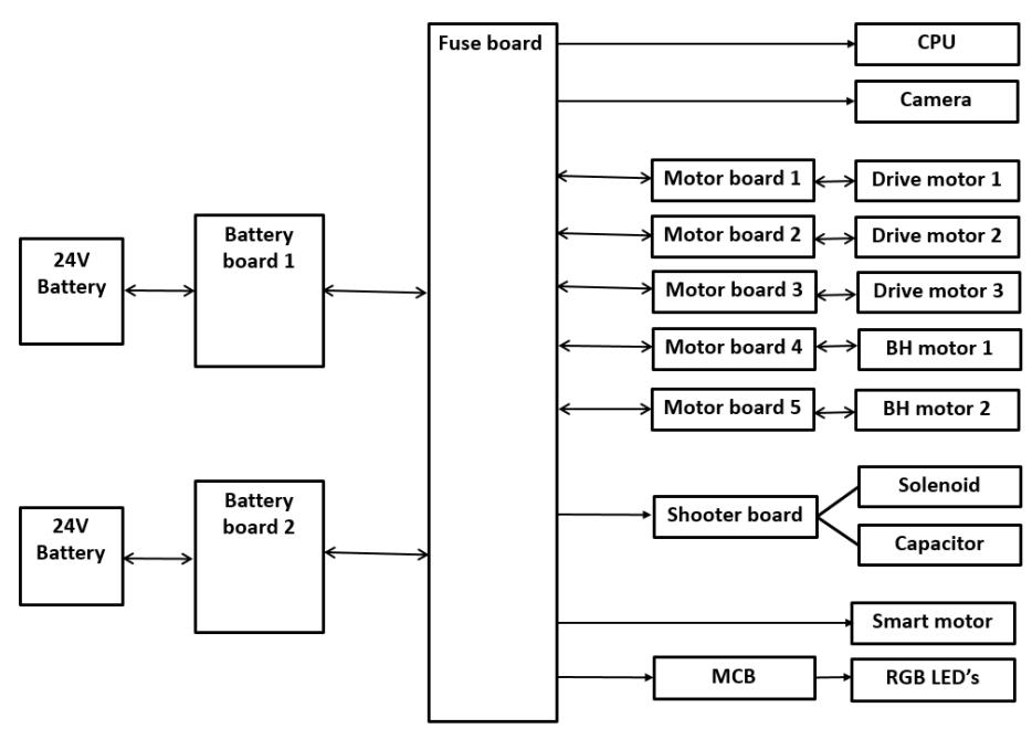
Power is still drawn from two 24V 4AhNiMh batteries. Directly after each battery, there is a PCB that contains a fuse, capacitors to prevent voltage drops when accelerating and inrush current limitation. Power is then transferred to the fuse board which contains fuses for every individual user and three relays for safety. For example, power for driving the motors is only supplied when a) no EMO button is pressed b) "in play" button is switched on c) software is running and gives OK signal. From there all users are supplied. If other voltages are needed, they are made on the boards locally. This reduces the amount of cables in the robot.
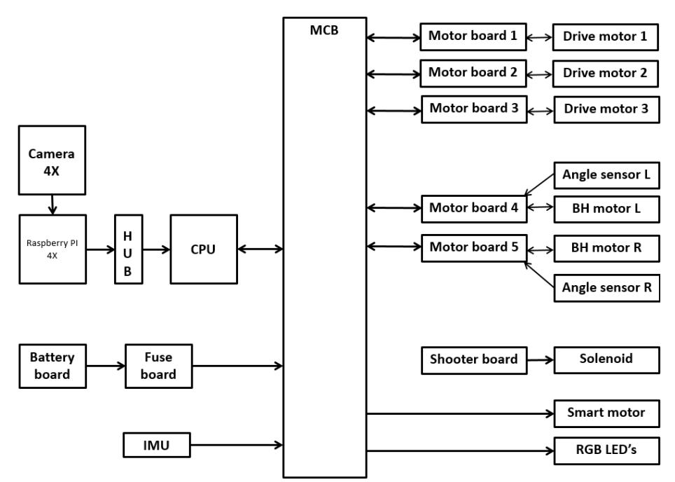
In last year's prototype, the motion architecture was changed to a more advanced control system, containing the Maxon EPOS4 motor controllers in combination with a Motion Control Board (MCB). To achieve higher control loop bandwidth and better control. This is described in detail in the Team Description Paper of 2019[CITATION Edw19 \l 1043 ]. Improvements are made to improve the stability of the communication. It was proven difficult to have a stable update frequency towards the control boards. Also the communication between the CPU and the MCB was changed from Ethernet to USB because of easier implementation. In future improvements, this might be changed back to Ethernet.
To detect spinning wheels, or wheels turning while not on the ground after a collision, an Inertial Measurement unit was added and connected to the MCB. The information is fused with the feedback from the motor encoders. This will improve the localization while driving and decrease the risk of a "flip" of the robot in a game. This happened regularly during test matches and tournaments.
Another function of the MCB will be the function of the IO board. Therefor the MCB will provide the control signals for the colored RGB LED's on the robot identification numbers. At the moment it's not decide if the input will be a switch or handled by software on the CPU. The MCB will also control the shooter coil, shooter height mechanism and battery voltage monitoring.
The height adjustment is changed from a stepper motor in the current design to a smart motor in the new design. Main advantage is that the smart motor is lighter, doesn't need a separate driver, has no holding current and has encoder feedback. This gives more flexibility on where to place it and gets rid of the homing stroke after a shot. The homing movement was needed because the shooter coil moved the stepper motor away from the intended position, but this was not compensated. The setpoint will come from the CPU, the MCB converts the setpoint to the correct protocol and
the logic in the motor will move to the desired position and keep the motor at this position. Schematics of the electrical design are shown on the next page.
References
- Schreuder, E. (2020, 01 14). Falcons Team Description Paper 2019. Retrieved from http://falcons-robocup.nl/images/Qualification-2019/falcons_team_description_2019.pdf
- Vos, J. (2020, 01 14). Qualification material 2018. Retrieved from falconsrobocup.nl: http://falcons-robocup.nl/images/Qualification-2018/falcons_team_description_2018.pdf