LAR@MSL Description Paper 2023
António Ribeiro, Joel Costa, José Martins, Rúben Silva, Rui Lima, Carolina Lopes, Gil Lopes, A. Fernando Ribeiro
Laboratório de Automação e Robótica (LAR) DEI - Universidade do Minho Campus de Azurém, 4800-058 Guimarães, Portugal
Abstract The LAR@MSL team has been participating on MSL for many years, from 1999-2007, 2011, and 2016. After a few years of stoppage for RoboCup nonrelated reasons, the research team is back to the MSL with a new generation of students. The 2016 robot platforms are being used with some hardware/software changes as the robots were very obsolete and the changes were needed to keep up with the league evolution. This Team Description Paper intends to briefly explain the robot's structure, hardware and software and some of the most important changes implemented by this new team. It is important to point out that all the team students are new to the league, even though some of them already participated on RoboCup Soccer Junior just a few years ago. As electronics engineering students, most of the changes carried out were on the electronics and on the code, and the mechanical parts were left almost left untouched. The motors, cameras, kicker board and chassis are the same as the 2016 generation. Regarding the software, a ground up rebuild was carried out as the game strategy new attempt was very different from the previous team. This paper describes a bottom-up view of the robots, the hardware used, the vision head, the low-level software and strategy and finishes with some conclusions. The whole code and the hardware description are available on a public GitHub repository.
1 Introduction
The Laboratory of Automation and Robotics belongs to the School of Engineering of the University of Minho, Guimarães, Portugal, and his first participation on RoboCup MSL was in 1999. Previously known as MinhoTeam, the LAR@MSL new name contains the research Laboratory LAR name (Laboratory of Automation and Robotics) and addresses the MSL league, as the LAR also participates on other RoboCup leagues (like @Home). This new generation of students working on the MSL team just started this academic year (back in September 2022) and intends to gather new students for the coming years to continue participating in the MSL league. The robots were completely built in the LAR along the years (mechanics, electronics, and software) and all 5 robot's code is the same, with some parameters to distinguish the goalkeeper.
2 Hardware
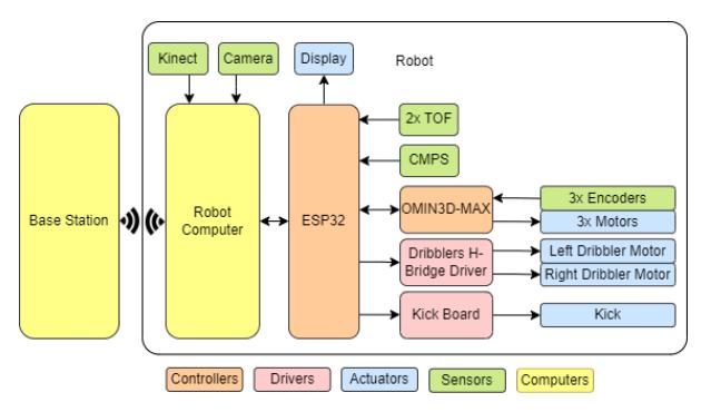
The general robot diagram (Figure 1) uses colours to distinguish between Computers, Controllers, Drivers, Actuators, and Sensors. The robot computer and the Base Station are two computers which communicate via Wi-Fi. The Base Station is responsible for processing the strategy and send all the commands to the robot Computer. Then, the robot Computer processes all received information by both the Base Station and the robot sensors, and afterwards it sends commands to the ESP32. The ESP32 also receives data from 2 Time Of Flight Laser sensors and a compass CMPS14 and sends that information to the robot computer. After processing all the data, the ESP32 sends the desired output to the actuators and control boards.
2.1 Mechanics
Since the last team generation, the chassis of the robot stayed the same besides little changes by drilling the aluminium sheets to better organize the cables inside the robot. This decision of keeping the chassis was based on the limited time and the team budget.
2.2 Electronics
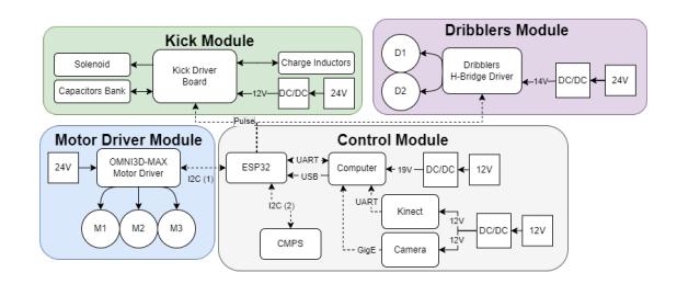
Each robot has a power distribution unit (called "PowerBox") which contains all electronic components, and it was developed to manage the energy flow, described on Figure 2. The system is energized with two different batteries in order to avoid interference generated by eventual actuators current peaks. Each circuit has its fuse for short circuits and overload protection. The converters used for each component power demands were selected as follows:
- Computer 400W boost converter with overcurrent protection;
- GigE BlackFly camera, Kinect and relay module 10W buck converter;
- Dribblers module 300W buck converter with adjustable output current;
- Kick module 70W DC/DC converter with 12V 6A output.
For safety reasons the included relay module allows disabling the OMNI3D-MAX motor driver board remotely. The kick board has a safety mechanism to discharge the capacitors which consists of a button on the PowerBox, and a LED representing the capacitors state.
3 Software
The software can be described as:
- High Level The Base Station and Strategy;
- Middle Level Robot Skills and Vision;
- Low Level Microcontrollers that control the sensors and actuators.
3.1 Low-Level
The Low-Level software is the one inside the ESP32 microcontroller, and is responsible to receive the commands from the main computer, to collect the sensors data and give them back to the PC and to control each actuator. The choice for the ESP32 was based on its low price, high performance, reliability, and the Bluetooth and Wi-Fi modules already integrated. Even though these modules are not used during the game, they are an excellent tool for debugging and demonstrations.
3.2 Middle-Level
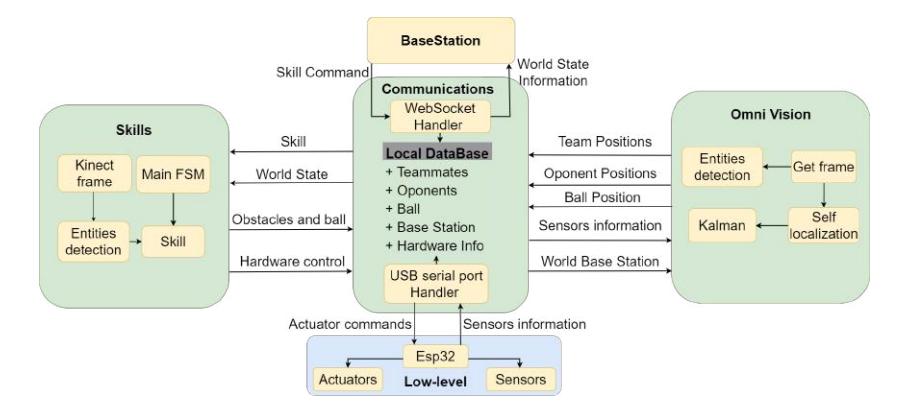
The Middle-level software is the robot brain. It commands the whole robot to perform its localization, motion behaviour and skills. The software for each robot can be divided into three different modules: the communications module, the localization module, and the skills module. A thread is used for communications to receive the frames sent by ESP32 through the serial port, to send the information from the robot sensors, as shown in Figure 3. Another thread is used to handle the communications with the Base Station, established through a WebSocket over UDP protocol. The Base Station sends to each robot the strategy commands to assign skills during a game. On the other hand, the world seen by the robot is sent to the Base Station every 50 ms, as a result of the information gathered by the robot sensors.
There are six skills that a soccer robot can perform during a game: Move, Attack, Receive, Kick, Cover and Defend. The commands sent by the Base Station choose which skill the robot must perform with specific parameters. From then on, the robot will autonomously perform its skill. The skill Receive is performed when the robot is receiving a pass from a teammate. Kick is the skill performed when the Base Station indicates a pass to another player or to shoot to the goal. The Attack is the skill performed when the robot must gain possession of the ball, whether it is lost or in possession of an opponent. The Cover is the skill performed when it is necessary to cover a pass line. The Move is the skill used when the robot needs to position itself in a certain region of the field. The skills mentioned so far use different control systems, like PID control and non-linear dynamic systems for the Move for example. PID control is used to control situations where high precision in a movement is required, such as when receiving a pass. On the other hand, during movement on the field, non-linear dynamic systems become a better option, where the destination is the attractor and the obstacles are repellers.
3.3 Vision Systems
The robot vision head is responsible for retrieving the coordinates of all elements on the field, making it possible to plan the strategy and coordinate the team effectively.
Omni Directional Vision System
The robot vision head is responsible for retrieving the coordinates of all elements on the field, making it possible to plan the strategy and coordinate the team effectively. To achieve this, a catadioptric omnidirectional system consisting of a GigE BlackFly camera facing upwards to the centre of a convex mirror (Figure 5 a)) is used. This apparatus allows easy self-localization and detection of surrounding game entities. The YOLO framework is being integrated into the system to detect game entities. Despite consuming a lot of computational resources, the YOLO results are promising. Instead of using simple detection that returns a bounding box, segmentation is being tested, returning the contours of all game entities in addition to classifying them, making it more accurate to calculate the distance to objects, as shown in Figure 5. All tests were made using YOLOv8 (small), and the trained classes include robots, balls, humans, and goal posts. The GPU used for detection has been an NVIDIA GeForce GTX 1650 (Laptop) and it takes 7 milliseconds per inference. This method is also being tested for self-localization through the distance to field objects, which allows obtaining the coordinates without using conventional MSL field lines. This facilitates demonstration and testing in any location as long as it has a reference point. In in-game situations, this method will be used to improve self-localization and coordinate the team more effectively.
Kinect
Front vision is used mainly by the Skills module in order to locate the ball and other game entities more accurately than omnidirectional vision. The Kinect was properly installed facing front with a tilt down angle of 16º, so that the images grabbed could detect when the robot has the ball and be able to process information far away from the robot. The RGB and Depth frames taken with the Kinect are used for the detection of the ball and obstacles by classical Computer Vision techniques using OpenCV. The ball colour and shapes are detected to calculate its position relative to the robot. Later, these detections will be carried out with YOLO algorithms using segmentation, which will return the detection contours.
Ball 3D trajectory prediction
In order to reduce reaction time and increase performance, the goalkeeper is able to predict the ball trajectory, based on an RGB-D camera (Kinect). Using computer vision to detect the ball and the distance channel to get the distance to the ball, the system takes two frames to obtain the ball coordinates relative to the goalkeeper. With those coordinates, the system uses linear equations to obtain the ball trajectory. After the system captures the two frames, the first thing is getting the number of pixels between the ball and the centre of the image. Then, knowing the field of view of the camera and the resolution of the image, the angle between the ball and the centre of the image is calculated. With that angle, using the depth image from the Kinect (K1), it is possible to compute the distances L1, L2, D1 and D2 represented on Figure 4. The distances are the coordinates of the ball in the two consecutive frames, making it possible to obtain the slope and y-intercept, that will give the equation to the ball trajectory.

3.4 Localization
To self-localize, with the Omni Vision System, the field lines (Figure 5 b)) are converted into a real distance map (Figure 5 c)), which is rotated at the same angle as the robot orientation. This map is then compared with a game field predefined map (Figure 5 d)). However, due to the oscillating values of the obtained coordinates, odometry and a Kalman filter are used to improve precision and stability. Although the obtained results are promising, different methods will further be tested to improve the matching with the map.

Goal-Keeper position (LiDAR)
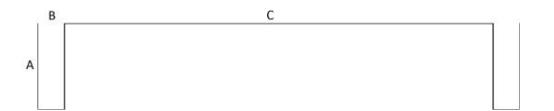
To find the goalkeeper position, a LiDAR was placed at the back of the robot. The model is a URG-04LX, which has a detection range of 240° and 4 meters distance. The step angle is 360°/1024 (approximately 0.36°), the distance resolution is 4095 (over the maximum of 4 meters) and takes 100 milliseconds per scan (10 scans per second). The LiDAR data is represented as an image, placing white dots with the respective angle increment and distance relative to the centre, as in Figure 7. At this point, the image is drawn with the angle shift indicated by the compass to avoid additional post-processing. The location method consists of executing a template matching over the previously described image. The template is shown on Figure 6, and it is generated by resorting to the three represented goal parameters: depth, post width and distance between posts. The template matching algorithm used is the normalized cross correlation, which allows to easily apply a threshold. With the reference points calculated, trigonometric methods are applied to find the goalkeeper position relative to the middle of the goal line and absolute coordinates on the field.
4 Base Station
Base Station section covering simulator, communications, and strategy.
4.1 Simulator
In order to speed up the code development, the team created a simulation environment able to recreate specific plays, develop strategies, play games and even test the communications system. The simulation environment was developed with the Webots framework and the code inside it developed using python. The environment has 10 robots, 5 from each team, that are able to move, dribble and kick the ball. The setup also allows human robot control for every robot, which allows having 5 humans controlling one team, and play a game against the strategy developed. The simulation world is 3D, so that when arc kicks are possible by the robots, the environment is already prepared for that ability.
4.2 Communications
The communications system between the robot and the Base Station uses UDP WebSockets. Even though WebSockets are bidirectional, each communication between the Base Station and a robot has 2 sockets. Each socket only transmits data one way, to allow different data frame frequencies and avoid overflowing the buffers on each side, and also more data control is achieved regarding information transfer. The Simulation communication system is fully compatible with the communication between the Base Station and the real world robots, simplifying the transition between the simulator and the real robots.
4.3 Strategy
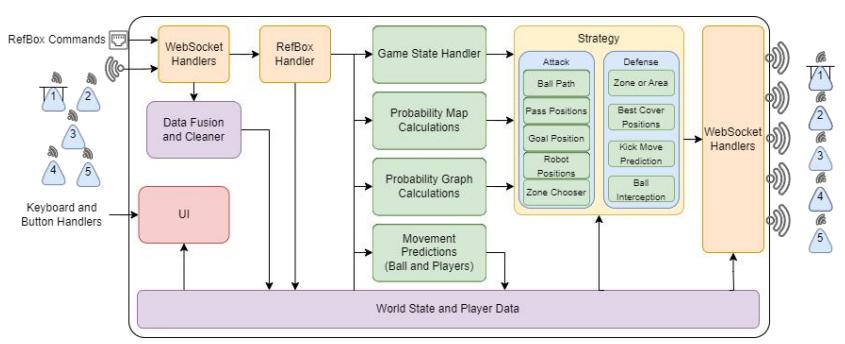
Unlike the previous team generations, a centralized strategy was implemented on the Base Station Computer, giving out commands to every robot on world state changes. The world state changes are simple changes in the game, like who has the ball, where are the opponent team robots, RefBox commands, etc. On every iteration, the Base Station receives new world information given by the 5 robots, allowing the Strategy to calculate all necessary inputs to make game decisions visible on Figure 8.
Ideal Play Calculator
The Strategy calculates the likelihood of every action possible like pass and kick to the goal based on Bell Curves. All the calculated values are translated to arbitrary values using the logarithm of a probability to optimize the system performance and apply the A* algorithm to calculate the best ball path to score a goal.
Heat Maps
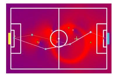
Heat probability maps are used to calculate the best position possible for each robot at every situation. These maps are created, associating positive and negative values to every position based on the map entities and the ideal solution previously calculated. For example, it is ideal for the robots to always be between the ball and one opponent team robot, so the values near the enemy robot are positive in the front and negative on the side opposite to the ball. An example of these maps can be seen on Figure 9.
5 Conclusions
This paper presents a brief introduction to LAR@MSL. Since the team was forced to a halt over these last few years due to RoboCup nonrelated reasons, there was a lot of hard work that needed to be carried out. It was necessary to understand what previous MinhoTeam generations developed and repair hardware before anyone could actually work on the robots again. The first and obvious need was the redesign of the Power Box and batteries. Then it was decided to add a depth camera - the Kinect - to detect the ball and obstacles on the field in 3D and more accurately. Using the Omni Vision camera, all the field detection and self-localization algorithms were refined and new filters were applied so that template matching was at its best. Meanwhile, a simulation tool was developed to develop code and strategy even before the robots were fully functional. This development also made possible to recreate games based on log files acquired from previously played games and to play against the team strategy while controlling the opponent team using 5 remote gamepads. Using the information gathered from the robots, the Game State Handler is responsible for deciding what is the active game state and making the robots respond accordingly. The strategy is being developed based on Probability Maps, Path Graphs and Movements Prediction. The LAR@MSL public repository is available on GitHub (https://github.com/LARobotics).
References
- P. Lima, A. Bonarini, C. Machado, F. M. Marchese, C. Marques, F. Ribeiro, D. G. Sorrenti, Title: "Omni-Directional Catadioptric Vision for Soccer Robots", Special Issue of the Robotics and Autonomous Systems Journal, Elsevier
- Daniele Nardi, Itsuki Noda, Fernando Ribeiro, Peter Stone, Oskar von Stryk, Manuela Veloso, "RoboCup Soccer Leagues", AI MAgazine, Vol. 35, No. 3, pag.77- 85, DOI: http://dx.doi.org/10.1609/aimag.v35i3.2549, Fall Issue, 2014.
- Nino Pereira, António Fernando Ribeiro, Gil Lopes, Daniel Whitney, Jorge Lino, (2016),"Path planning towards non-compulsory multiple targets using TWIN-RRT*", Industrial Robot: An International Journal, Vol. 43 Iss 4 pp. 370-379.
- Fernando Ribeiro, Ivo Moutinho, Pedro Silva, Carlos Fraga, Nino Pereira, "Vision, Kinematics and Game strategy in Multi-Robot Systems like MSL RoboCup", RoboCup'2004 – Team Description Paper, RoboCup'2004
- Fernando Ribeiro, Gil Lopes, João Costa, João Pedro Rodrigues, Bruno Pereira, João Silva, Sérgio Silva, Paulo Ribeiro, Paulo Trigueiros, "Minho MSL - A New Generation of soccer robots", ", RoboCup'2011 - Istambul, Team Description Paper, Julho 2011.