Tech United Eindhoven Team Description 2023
A.S. Deogan, S.T. Kempers, D.M.J. Hameeteman, R.M. Beumer, J.P. van der Stoel, J.J. Olthuis, W.H.T.M. Aangenent, P.E.J. van Brakel, M. Briegel, D.J.H. Bruijnen, R. van den Bogaert, E. Deniz, Y.G.M. Douven, T.J. van Gerwen, G.P.M. van Hattum, K.A. Knapik, A.A. Kokkelmans, J.J. Kon, K. de Koning, G.B.A. L´evy, P.H.E.M. van Lith, H.C.T. van de Loo, K.J. Meessen, F.B.F. Schoenmakers, J. Selten, P. Teurlings, F.J.A. Vlaar, M.J.G. van de Molengraft
Tech United Eindhoven
Abstract The Tech United Eindhoven Middle-Size League (MSL) team is a six time world-champion, and achieved first and second place in the technical and scientific challenge of RoboCup 2022, respectively. In the past year, the team has made a considerable amount of developments in: a new swerve drive platform, incorporating semantic information in the decision making process, implementing dynamic through balls, and the detection of bouncing balls.
1 Introduction
Tech United Eindhoven represents Eindhoven University of Technology (TU/e) in the RoboCup competition. The team joined the Middle Size League (MSL) in 2006 and played in 13 finals of the world championship, winning them 6 times. The MSL team consists of 4 PhD, 7 MSc, 1 BSc, 7 former TU/e students, 7 TU/e staff members, and 2 members not related to TU/e. This paper describes the major scientific improvements of the Tech United soccer robots over the past year and elaborates on some of the main developments for future RoboCup tournaments. The paper starts with a description of the fifth generation soccer robot used during the RoboCup 2022 competition in Section 2. In Section 3 the developments on the swerve drive platform are described. Section 4 elaborates on how we will increase the level of semantics in our strategy. The work on more dynamic passes and detecting bouncing balls is briefly described in Section 5. Finally, the paper is concluded in Section 6, which also presents our outlook for the coming years.
2 Robot Platform
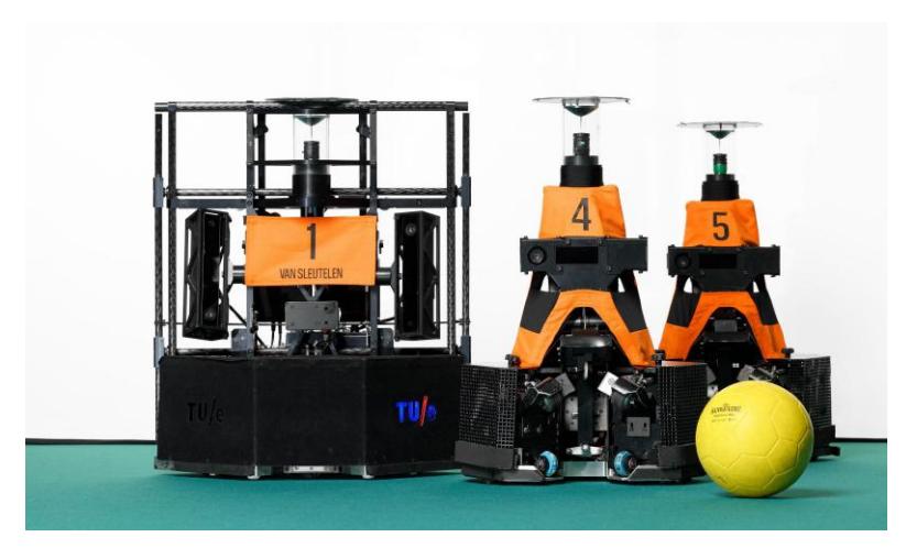
The Tech United soccer robots are called TURTLEs, which is an acronym for Tech United Robocup Team: Limited Edition. Their development started in 2005, and through years of experience and numerous improvements they have evolved into the fifth generation TURTLE, shown in Fig. 1.
The software controlling the robots consists of four modules: Vision, Worldmodel, Strategy, and Motion. These modules communicate with each other through a real-time database (RtDB) designed by the CAMBADA team [1]. The Vision module processes the vision sensors data, such as omni-vision images, to obtain the locations of the ball, opponents, and the robot itself. This position information is fed into the Worldmodel. Here the vision data from all the team members is combined into a unified representation of the world. The Strategy module makes decisions based on the generated worldmodel using the Strategy, Tactics and Plays (STP) framework [4]. Finally, the Motion module translates the instructions from Strategy into low-level control commands for the robot's actuators.
3 Swerve Drive Platform
The RoboCup MSL matches take place on flat, homogeneous surfaces and are primarily focused on strategic and autonomous multi-agent decision-making at high velocity. Humans, on the other hand, are able to manoeuvre on a wide variety of terrains, where bumpy soil and tall (wet) grass are no challenge at all. Most teams equip their platforms with multiple (mostly three) omni-directional wheels, having the drawback of requiring flat surfaces due to the limited radius of the small rollers on the perimeter. Additionally, more uneven or slippery surfaces result in slipping motion or even getting stuck. The goal of RoboCup is to win against the winner of the human World Cup in 2050. Therefore, it is important that the robots are able to play on more diverse and outdoor terrains, and achieve high maximum accelerations and velocities in all directions.
3.1 Hardware Design
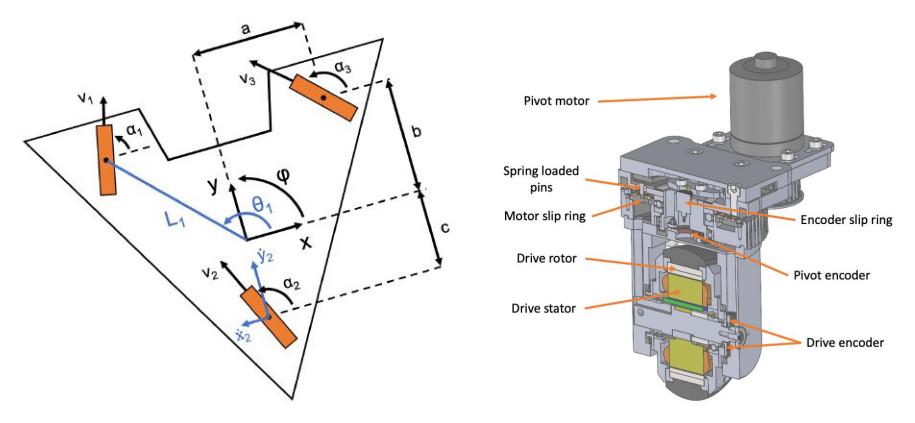
The swerve drive principle [3] looks promising, especially when considering the significantly larger contact area between wheel and surface. Equipped with separate steering actuators, these platform can take full advantage of their acceleration capabilities, since 'normal' wheels have larger contact surface (and thus friction) than the small rollers of omni-directional wheels. Fig. 2a shows the graphical representation of the swerve drive platform, consisting of three wheelsets.
Fig. 2b shows the compact design of a single wheelset, consisting of the drive motor and the pivot motor. Direct-drive in-wheel brushless DC (BLDC) motors are found in a wide variety of electrical scooters and skateboards and form the basis of the wheelset design. Since space is very limited, the wheel and drive motors are combined into one module. The inner-coils of the motor control the outer magnets, which in turn is attached to the tire.
One major challenge is to provide high power to the drive motor since the wheel rotates 360° together with the pivot axis. It is undesirable to limit the possible amount of rotations, therefore twisting wires through the centre of the pivot is not feasible. Since the motor requires a considerable amount of current, at least 15A RMS, special slip rings have been developed. Three brass rings, one for each BLDC motor coil, are put together in a single disk, with the motor wires assembled to one side of the ring. Spring loaded pins are pushed against the other side of the ring, which bridges the gap between the rotary and stationary side.
The secondary motor, attached to the propulsion motor, is responsible for rotating the wheel around its own axis. Again, a low-cost BLDC outer runner motor was chosen that is widely available within the consumer market. Since the pivot angle demands high torque (and lower maximum velocity), the motor is connected through a belt transmission with a gear ratio. The wheelset has been designed such that three identical sets could be created: one for each corner of the platform.
Communication between the main PC and motors is established via Ether-CAT, with the real-time capabilities. The position and velocity of each motor needs to be obtained for accurate control of the overall platform. Most off-the-shelf high resolution encoders are either not accurate enough, built rather bulky, or are expensive. Therefore, a small PCB for accurate 19-bit encoder positioning was developed in collaboration with SMF KETELS. A magnetic ring with a unique pattern is centred on the rotating side, while the encoder chip is placed off-centre against the stationary side.
3.2 Software Design
First, each of the motor drivers needs to be configured by saving information about the motor, gear ratio, encoders, and low-level control structure in the driver's Service Data Object (SDO) dictionary. Furthermore, the Process Data Object (PDO) map has to be assigned such that the device knows which registers should be available for reading and writing real-time data. Configuration and communication between the master controller and the motor driver slaves make use of the Simple Open EtherCAT Master (SOEM) library. The library provides an application layer for reading and writing PDOs, keeping the data synchronised, and detecting and managing potential errors.
The motor drivers are already capable of performing cyclic synchronous position and cyclic synchronous velocity mode based on the low-level setpoints. What remains is to calculate the setpoint position for the pivot motor and setpoint velocity for the drive motor.
Fig. 2a also shows the kinematics of each wheelset, composed of a position and centre of rotation with respect to the platform's centre of rotation, which is known by design. These positions are used to calculate the polar coordinate position of each wheelset, represented as radial distance $L^i$ and polar angle $\theta^i$ with respect to the platform's x-axis, where $i \in {1, 2, 3}$ corresponds to the wheelset.
Next, the desired platform reference velocity $[\dot{x}\ \dot{y}\ \dot{\phi}]_{\rm ref}^{\top}$ can be used to calculate the velocity $v_i$ and pivot orientation $\alpha_i$ of each wheelset. More information will be available on the ROP wiki.
3.3 Results
The swerve drive platform was presented for the first time during the MSL Technical Challenge at RoboCup 2022 and achieved first place. The results are very promising as the prototype showed great performance in terms of acceleration and robustness on uneven, bumpy terrain. Currently, the acceleration is limited by the motor drivers, which are not capable of delivering more than 30A peak. The goal for this year is to turn the prototype swerve drive platform into a fully functional robot able to participate during the RoboCup 2023 and potentially scoring its first goal.
4 Decision Making Through Semantic Regions
In the game of soccer, strategy has a significant contribution to winning games. The effectiveness of a strategy is dependent on the capability of the players and the opposing strategy. In human soccer this is developed over the years and comprises the formation, the type of build-up, the width of play and many more qualitative notions [2]. In the context of the RoboCup MSL, the strategy and configuration of this has been solved in various ways [6,7]. Currently, the Tech United team uses Skills, Tactics and Plays (STP) as the overall strategy framework [4]. This method provides individual robots with a task to contribute to the strategy. However, ad-hoc decisions still have to be made to react properly to the specific situation of the game. These decisions consist of choosing a skill and target to execute the task, e.g. 'shoot', 'pass' or 'dribble' in case of the player in possession of the ball. Currently, this is solved by artificial potential fields, named mu-fields. These mu-fields correspond to a weighed sum optimisation function [5]. The skills are subject to a set of constraints, e.g. a player is not able to pass the ball behind an opponent. At this moment these are formulated as optimisation objectives, hence no distinction is made between feasibility (discrete) and quality (continuous) of the solution. A spatial representation of the skill's feasible design space in the world model (2D) of the robots is created to solve for this [5]. The method 'Semantic Map Decision Making' subtracts constrained regions from the initial skill region, e.g. the outline of the field, to produce the feasible space for every skill. Consequently the constraints are already accounted for when performing the optimisation, since only feasible spaces are regarded. As the weights of the objectives are tuning parameters, reducing the amount of them enhances the configurability of the strategy.
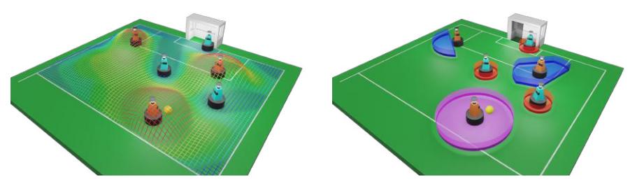
In Fig. 3a the current mu-fields are visualised. For every position a utility function is calculated, $U = \sum_{i=1}^{k} w_i f_i(x)$. This function is evaluated over a discretized field (grid). Examples of objectives are: the distance to the goal, and the positions behind an opponent (from the ball's perspective). The latter is described as a constraint in the introduced method and is thus taken into account when creating the semantic map where it confines the feasible space. This is visualised in Fig. 3b. Here the feasible spaces for every possible skill of the robot in possession of the ball are shown.
According to the task that a robot is equipped with, it has a set of possible skills to execute the task. The introduced methodology provides decision making between these skills. It includes the spatial constraints of every skill in the world model of the robot, thereby the feasible space of each skill is defined. This results in less positions to evaluate and less objectives in the optimisation, thus enhancing the configurability.
5 Miscellaneous
[Placeholder for section intro if any]
5.1 Through Balls
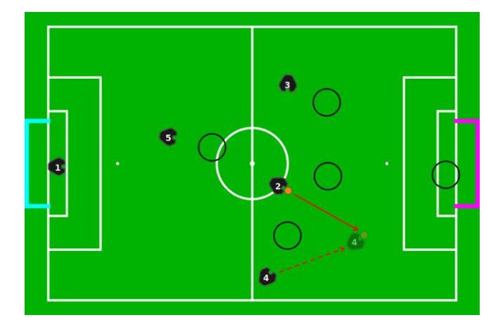
Through balls make the gameplay more dynamic compared to passing the ball to a stationary robot. We define through balls as passes into open space, either through a gap between opponents (as shown in Fig. 4) or not. Adding this type of pass creates more opportunities to give a pass. Another advantage is the distance the receiver can already cover before receiving the ball, which makes it more difficult for the opponent to defend.
The pass target is determined by a multi-objective optimisation, for instance taking into account the opponents' positions and the distance from the pass target to the opponent goal. The optimisation is currently performed by the mufields, but could also be based on semantic regions, both explained in Section 4. When a pass target is found that is considered to be better than dribbling or shooting, the robot in possession of the ball kicks it and the other robot moves towards the agreed target to receive it.
5.2 Bouncing Ball Detection
When looking at 'normal' human soccer, one can see the significance of playing through the air; headers, corners, and lob passes are all common aspects of soccer. As a first step towards expanding our capabilities of playing through the air, we want to focus on detecting if a ball is bouncing.
The most important aspect of the bouncing ball detection is the use of a Kinect camera instead of the omnivision camera. This allows the robot to observe the 3D position of the ball. This position is then fed into a Kalman filter, which predicts the vertical position based on a simple gravitational model. Bounces on the ground are incorporated using inflatable noise variance. When the ball hits the ground, the noise variance is artificially increased as to follow the camera measurements for a few samples. The noise variance then quickly (usually in two to three measurements) converges to the working values again. The filtered vertical positions of the ball are then fed into the bouncing ball detection algorithm.
To determine whether a ball is bouncing, our software module now tracks the (absolute) vertical position and velocity of the ball. The module evaluates whether the ball's position, velocity and acceleration are below their corresponding thresholds, which are tunable parameters. If all three checks return true, then the ball is said to not be bouncing. The third check is necessary to distinguish the extrema (lowest and highest points) of the bouncing ball trajectory from a ball suspended in the air. With this simple module we are able to detect whether a ball is bouncing. Based on this information the robots will wait for the ball to finish bouncing, before intercepting it. Future steps will be to predict the trajectory of the ball, which will allow us to perform headers and to receive passes through the air.
6 Conclusion
In summary, the major scientific developments of the Tech United soccer robots over the past year have been presented. Using a new platform that utilises the swerve drive principle allows the robots to manoeuvre on more rough and uneven surfaces, while achieving a higher acceleration and top speed. Almost certainly, this platform will participate in its first match at RoboCup 2023. In line with the goal set in 2050, this advancement provides a step towards playing on a grass field.
A more configurable design of the decision making process was discussed. By incorporating semantic information, a more explainable and straightforward implementation of new plays can be gained. The skill of through ball passes was integrated into the capability of the robots, improving the flow and dynamics of the game. Considering that these passes are often used in human soccer, the game play will also look more natural following this development. Finally, a method for detecting bouncing balls was presented. The presented progress contributes to an even higher level of dynamic and scientifically advanced soccer competitions during RoboCup 2023 in Bordeaux, France.
References
- Almeida, L., Santos, F., Facchinetti, T., Pedreiras, P., Silva, V., Lopes, L.S.: Coordinating distributed autonomous agents with a real-time database: The CAMBADA project. In: Computer and Information Sciences - ISCIS 2004. pp. 876–886. Springer Berlin Heidelberg, Berlin, Heidelberg (2004)
- FIFA: Futsal coaching manual (June 2019)
- Holmberg, R., Slater, J.C.: Powered caster wheel module for use on omnidirectional drive systems (12 2002), http://www.google.it/patents/US4741207, uS Patent 6,491,127
- de Koning, L., Mendoza, J.P., Veloso, M., van de Molengraft, R.: Skills, Tactics and Plays for distributed multi-robot control in adversarial environments. In: RoboCup 2017: Robot World Cup XXI. pp. 277–289. Springer International Publishing, Cham (2018)
- Marler, R.T., Arora, J.S.: Survey of multi-objective optimization methods for engineering. Structural and multidisciplinary optimization 26(6), 369–395 (2004)
- Neves, A., Amaral, F., Dias, R., Silva, J., Lau, N.: A new approach for dynamic strategic positioning in RoboCup Middle-Size League (09 2015). https://doi.org/10.1007/978-3-319-23485-4_43
- Reis, L.P., Lau, N., Oliveira, E.C.: Situation based strategic positioning for coordinating a team of homogeneous agents. In: Balancing Reactivity and Social Deliberation in Multi-Agent Systems. pp. 175–197. Springer Berlin Heidelberg, Berlin, Heidelberg (2001)