UM CROATIA team description paper
Filip Kuzminski, Petar Slaviček, Jurica Vučković, Matko Pribičević, Jaša Kocijan, Viktor Mirić, Antonio Ćuk, Demion Šavrljuga, Vedran Zović, Tea Kukec, Ana Vuković, Marija Vuković, Noa Šoić
Faculty of mechanical engineering and naval architecture University of Zagreb; University of Zagreb Faculty of Electrical Engineering and Computing; University of Zagreb, Faculty of Humanities and Social Sciences
https://www.udrugamehatronicara.com/
Abstract UM CROATIA is a student team that started making MSL robots in 2022. Students are divided in teams that do software, embedded hardware and mechanical engineering and a marketing team that does fundraising for robot and going to competition. The team is focused on low budget design and does a lot of robot part production in house. Robot electronics for motor control and power supply are also made in house. The main goal of team is to allow students to work on cool projects and gain knowledge in mobile robotics and industrial systems.
Keywords: RoboCup Soccer · Middle-Size League · Autonomous mobile robots
1 Introduction
UM Croatia targets competing in Ambition challenge which would allow the team to compete after a year a half of building the robots and software. By the time the competition comes, the team plans to have at least two fully functional robots that are able to follow the simplified rules presented in Ambition challenge. In the following chapters, the robot construction, electronics and software chart are presented.
2 Robot construction
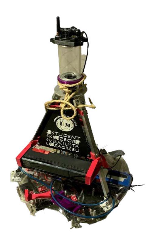
The robot is made of 3 different bases:
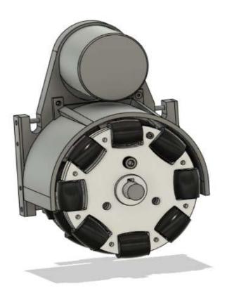
- The first base, where all motion components are located with two 6S LiPo 5000 mAh batteries in the middle, close to ground to keep low center of gravity. The 4 motors with 100 mm three-row omni-wheels are fully suspended with two damping shocks. Each suspended wheel construction consists of gear down system with reduction factor around 5. The shocks are connected to first base, so the whole first base can be disconnected from the rest of the robot. To the rest of the robot, only a power supply wire and CAN bus communication wire are connected.
- The second base has installed kicker and dribbler mechanism. The third base is connected to the second base with aluminum tubes.
- The third base encloses all the electronics in a raised platform. The Kinect camera is mounted on third platform. The platform ends with hyperbolic mirror coupled with FLIR camera and active beacon on top
2.1 Kicker mechanism
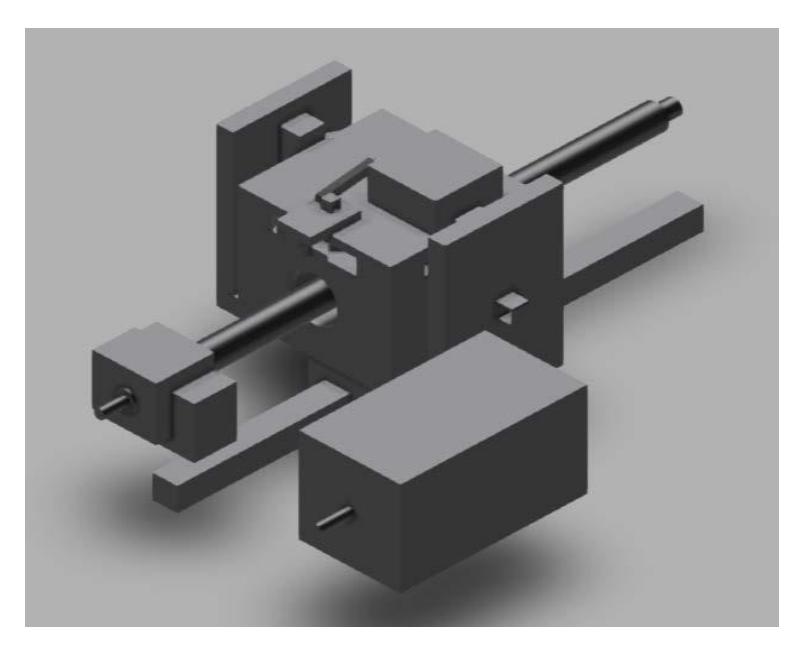
A mechanical kicker mechanism is being developed for the robot that uses underwater speargun latex rubber for energy conservation. In underwater spearguns, more than 200J of energy can be conserved when rubber is stretched. The current design preserves around 100J of energy that is ready to be transferred to the ball.
3 Robot electronics
Robot uses Nvidia Jetson Orin 32GB as main processing unit. It has auxiliary Arduino unit used for reading ADC signals from potentiometers used for detecting ball in robot when dribbler position is changed. Arduino also controls the preloading and releasing of kicker mechanism. Robot uses XBOX Kinect 2.0 camera to aid in ball detection and has a custom made hyperbolic mirror paired with 6mm lens and camera. All motors are controlled via CAN-bus communication and are driven with VESC brushless speed controllers. In order to power the 12V electronics, an isolated 60-12V DC-DC converter is made in house with total power output of 150 W.
4 Software
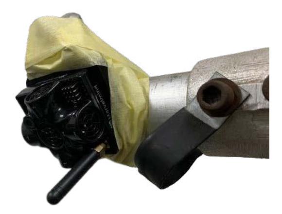
The robot software is built using Robot Operating System 2 (ROS2). There are three groups of nodes in our system: Input nodes, Output nodes and Control nodes. Each input (sensors, camera) has its own node that converts raw data to data formats used by other nodes. This includes a Spinnaker node that reads the catadioptric camera, nodes that preprocess the image and perform object detection, an I2C node that reads compass values as well as the Marvelmind indoor GPS node that outputs beacon coordinates and IMU data. Output nodes include a motor control node that communicates with all motors (drive motors, kicker and dribbler motors) over CAN bus. Control nodes include a HeadingPID node that reads IMU data and sets robot heading with a PID algorithm. Similarly, there is a PositionPID node that conrols robot position using indoor GPS data and IMU data. The main node is the robot core node that uses data from the input nodes to make decisions (following the ball, avoiding obstacles) and set targets for other control nodes (heading and position).

5 Conclusion
In order to make autonomous mobile robots on a custom platform, a lot of work needs to be done to make all robot systems made by different manufacturers to work together. This paper described how a robot architecture looks like after a year of work with no much prior experience in robotics. Still, after a lot of hard work and team work, a working well designed robot using simple tactics is possible to make when following previous work from other teams and information available online in robotics area. In future, a more robust localization system that does not depend on outside active beacons is to be made along with implementing the other rules from Robocup MSL rulebook in order to build fully autonomous soccer playing robots in near future that would be able to beat humans in a game of soccer.
References
- MSL Technical Committee 1997-2020: Middle size robot league rules and regulation for 2023 (2023), https://msl.robocup.org/wp-content/uploads/2023/01/Rulebook_MSL2023_v24.1.pdf