Team Description Paper: ERA-IITK
Emaad Ahmed, Dhruva Singh Sachan, Kartik Kulkarni, Rishi Agarwal, Debraj Karmakar, Mayank Agrawal, Nikhil Gupta, Ritesh Bavishkar, Suryansh Goel, Shivansh Mangal, Zehaan Naik, Nishi Mehta, Aditya Jain, Shubham Mittal, Tejas Chikoti, Yukkta Seelam, Ayush Ranjan, Siddhartha Watsa
Indian Institute of Technology Kanpur
Abstract ERA-IITK is based out of the Indian Institute of Technology Kanpur, located in India. We are a team of undergraduate students working towards developing autonomous robotics solutions for challenging problems. We are the first team (to our knowledge) from India to participate in the RoboCup MSL Challenge, and we aim to showcase our grassroots engineering on a global stage, simultaneously learning and having a lot of fun as a team!
Introduction
ERA-IITK is an autonomous robotics team founded in 2018, which originally participated in the DJI RoboMaster AI Challenge. WE participated offline in 2019 in Canada, achieving 3rd overall position and online in 2020 and 2022, achieving top 3 globally always. Since the competition was halted, we shifted our focus to RoboCup MSL. Working under tight budget constraints and limited faculty support due to being undergraduates, our design philosophy is based on cost-effectiveness and efficiency on the hardware front and low-complexity, innovative solutions on the software front. Having started in 2023, in less than a year we have managed to make significant progress that makes us believe that we would be a valuable addition to the league. We also aspire to see RoboCup Open competitions in India to further the spread of the competition to enable the core idea behind the competition- to encourage active research in the domain of autonomous robots and to allow people to witness the evolution of this amazing technology while enjoying it at the same time.
Mechanical Design
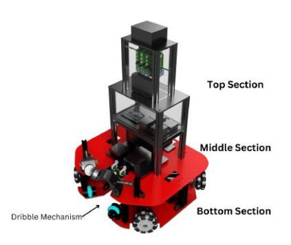
Keeping in mind the constraints on Robot Size, our bot has dimensions of 50cm x 49.5cm x 75cm with a weight of 20kg. We have opted for an all-aluminum design to get a sturdy and lightweight chassis. The bot design is divided into 3 sections as described below.
Bottom Section
In this section we have used a thick (6mm) Aluminum sheet which acts as a base for different components and aluminum extrusion for providing support to the top structure. Industry-grade Rhino 10kgcm IG52 planetary gear encoder motors are placed rigidly on the base plate in a diagonal fashion capable of providing a high-speed motion of 4m/s with precise holonomic drive. 100mm Omni wheels are attached to the motor using a coupling hub lock-key mechanism. The base plate also houses the battery, dual channel motor driver along with custom PCB for microcontroller-motor driver integration, and a custom solenoid with supporting wheels for dribbling. Details of the kicking mechanism and dribbling mechanism are described in subsequent sections.
Middle Section
The middle section houses the dribbling mechanism, a capacitor for the kicking mechanism towards the back, and a custom power distribution system on a 3mm aluminum base plate. It also acts as the base for placing the top section of the bot
Top Section
The top section is made up of aluminum extrusions and acrylic sheets. It has three levels where acrylic sheets are used as a base as well as covers to protect the components inside. The first level contains the Computing device (Jetson Orin NX 8GB) and a PCB for controlling the kicking and dribbling mechanism. The second level contains the Raspberry Pi 4 stack along with an ethernet switch box. Raspberry Pis are stacked using standoffs and fixed onto the acrylic sheet covers such that 4 Pi cameras on the 3rd level can be easily connected. Pi cameras are placed on a camera mount such that all 4 cameras are perpendicular to each other.
Kicking Mechanism
We are using a solenoid-based linear actuator along with a thin plate that acts as a kicker for the kicking mechanism. The thin plate has a cylindrical extrusion which is adjusted in such a way that it provides impact to the ball towards its center of mass. It also contains a slot to attach it to the solenoid actuator. The plate is pivoted at the middle plate. The solenoid is powered using a 450V 2700µF capacitor. An inverter relay is used to shift between the charging and discharging circuit.
Custom Solenoid
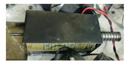
We have developed a custom solenoid having a stroke length of 5cm in a compact form factor. For the solenoid core we designed and 3D printed a cylindrical spoolshaped hollow cylinder having a length of 12cm, an inner diameter of 2cm, and an outer diameter of 6cm at the ends. We then used 23 AWG wire wounded 4000 times around the solenoid core and completed it by using a plunger of length 20cm tapered and threaded at one end for attaching it to the kicking plate. The solenoid-actuator system can kick a ball to a distance of 2m.
Dribble Mechanism
Our dribbling system contains 2 active wheels actuated using high-speed low torque N20 encoder motors. Two passive wheels are small trolley wheels attached in the lower base plate for providing support to the ball during motion. Active wheels along with the motor are mounted on a 3D-printed arm pivoted at the base which in turn is connected to an aluminum extrusion using a shock absorber. The angle of the arm can be adjusted by sliding the shock absorber on the aluminum extrusion, thus providing ease of adjustability. Two base plates are designed such that they allow the ball to come in contact with active wheels and the kicking plate. Shock absorbers allow the active wheels to put a little pressure on the ball further increasing the ball's maneuverability at high speeds.
Electrical Design
Subsequent sections provide details about the different electrical circuits and electrical components used in the robot.
Power Source
The robot is powered using a 20000 mAh 22.2V Li-Ion battery with a built-in battery protection circuit. The battery can provide a continuous power supply to the bot for 30 minutes on a single charge.
Power Distribution System
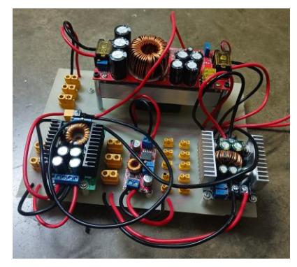
We have designed and developed a custom Power distribution system for efficient power distribution to the bot's various components. Our PDS consists of a PCB base on which a combination of bucks and boosts converters are placed to provide outputs of variable voltage ratings (19.2V, 12V, 9V, 5V) while ensuring appropriate current draw.
Custom PCBs
Apart from the Power Distribution System, we have also developed 2 more types of PCBs for integrating and controlling different hardware components.
Kicking and Dribbling Mechanism Circuitry
One of the PCBs contains two Arduino Nano Microcontrollers, an L298 Motor driver, and an optocoupler relay. One of the Arduino Nano is responsible for controlling the relay to activate the charging and discharging of the capacitor for the kicking mechanism. Another Nano controls the motors responsible for the dribbling of the ball.
Closed Loop Motion Circuitry
Another PCB contains an Arduino Nano microcontroller along with connectors and is used for controlling the IG52 Motors through dual-channel motor drivers. It also takes encoder feedback and sends it back to the Computing Device to provide a closed-loop control.
MultiCam Vision System
Inspired by the multi-camera system implemented by the Team FALCONS, we implement a similar setup to achieve robot Omni-vision. The system comprises of four Raspberry Pi v2 cameras (Sony IMX 219) with Fisheye lens (220 H) each connected to a Raspberry Pi model 4B. Ethernet switch is used to form a closed network between the four RPIs and the main Central Processing Unit (CPU) (Intel NUC Enthusiast 11). We preferred a MultiCam System over a Parabolic Mirror due to its several advantages, mainly the longer range of field view allowing an individual bot to continuously track opponent bots and gives the potential to track the ball even if it is airborne (future work), giving an advantage to the decision module to make more informed choices. Tracking far-away objects proved difficult in Parabolic mirrors due to the distortion from edges. Another advantage lies in the potential for scaling, all image processing, including object detection and tracking & sampling points from field lines, is carried out in Raspberry Pis. This added parallelism, even if it comes with the challenge of synchronization, we think is worth it due to the reduced load over the main CPU and resembles the way the human anatomy works, where different level of processing takes place at different organs to be combined at the brain.
Software Design
The software architecture comprises of multiple components which can be broadly classified into separate modules running concurrently on the RPIs and Main CPU respectively. The RPIs are responsible for extracting the relevant information from the images, i.e. the object trajectories and Field Lines, and conveying the information with time stamps to the main CPU, which combines them to maintain a State of the field. All bots communicate at a regular rate to share their local state of the field from their perspectives, and combining them leads to the World state of the field, to be used by the Decision Module as input. The World State of the field comprises of all the trajectories (current position and velocity) of the robots and the ball.
3-D object Tracking
We approach the 3D-Tracking Algorithm as a supervised learning problem [1] where the aim is to find N trajectories, where N is the number of object in view and is dynamic in nature. The algorithm receives detection from YOLOv8-tiny as input, and our task is to match the detections to their respective trajectories and update it according to the matched detection. Each trajectory defines the state of the object as s= P, Delta P, fapp, where P is Position Coordinates and DeltaP stands for its velocity. Fapp is the extracted features of the current detection and will be used to calculate similarity score with new detections. Finally, to associate trajectories with new detections an association score is calculated which takes into account the above similarity score & relative depth order making the algorithm more robust towards occlusion. Recurrent neural networks are used to update the state in the trajectory given five previous states. Another RNN is used to extrapolate the state in the time between current and new detection to improve the update rate of states.
Self-Localization
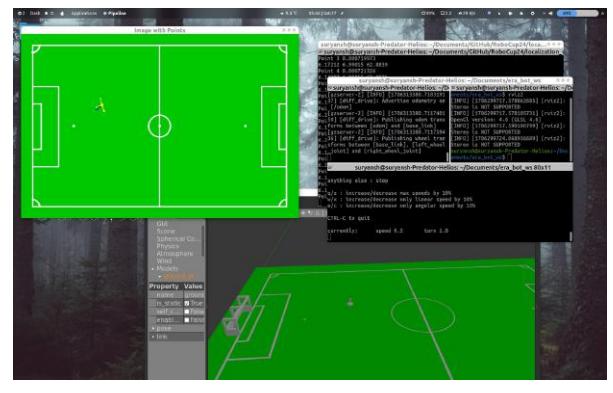
Like other teams in the competition, we use a white field-line-based localization algorithm. Our initial algorithm is based on Brainstormers' Paper [2], on top of which we have performed optimization and engineering at various levels. The codebase is written in C++ for quick execution and supported by the ROS2 [3] communication framework, tested on a Gazebo Simulation. The crux of the algorithm is extracting the White Line points from the field using camera parameters in the frame of reference of the bot, then using some initial pose estimate and optimizing a suitable defined loss function over the possible locations on the map where the bot could be. We employ suitably optimized Gradient Descent with an optimizer approach currently for loss minimization, although other methods are being evaluated by the team for better performance.
Once the global pose estimates have been acquired, we rank them according to their fitness and maintain a fixed number of estimates at all times, while also introducing a small number of new estimates and removing the least fit estimates at each time step to enable robustness. The removal criteria are based on the age of the points, their cost, and their closeness to their top estimates. This criterion has been derived experimentally. Each global pose is updated by the odometry received from the motor feedback after every iteration to achieve local localization. Once we are fairly confident of the global pose, we reduce the number of points in consideration and the number of iterations of the algorithm to improve the pose update speed and trust more in the odometry. This again, is experimentally verified. Problems like sudden flipping and noise are taken care of by a Kalman Filter and care is taken to ensure that the symmetry of the field does not cause problems. Below is an image of the simulation testing for the localization algorithm.
Controls and Motion Planning
This module forms the backbone of the gameplay. Its aim is to generate optimum control signals ensuring efficient traversal of each bot from its initial to final position. The codebase is written in C++ for execution speed and ROS2 [3] support. The algorithm was tested using a 3D Webots [4] Simulation. Webots [4] was chosen owing to its ease of use, scalability, popularity and open-source nature. A 2-layer control module consisting of a Low-Level Control and Trajectory Generation Module is implemented.
The Low-Level Control deals with the actual control of each individual motors to follow a given trajectory. As the robot has an omni-wheel drive, the kinematic model simplifies greatly, allowing independence of angular and linear velocities. The only constraint was provided by the motor's maximum rotation speed and torque, setting an upper bound for the speed and acceleration the robot can achieve. It was observed that it is always profitable for every robot to face the ball while travelling along its trajectory. This allows it to quickly receive or block passes. Hence, the designed control module maintains such an orientation yet having a negligible impact on the time taken to reach the target destination. Inspired from Thai, Ly and Dzung [5], a gain-scheduling based 3 PID Control was established, for controlling the net speed, normal velocity and angular velocity of the robot. The encoder feedback and the localisation module input was used to evaluate and minimise the error. The inverse kinematic relation,
$$\begin{pmatrix} v_1 \ v_2 \ v_3 \ v_4 \end{pmatrix} = \begin{pmatrix} -\cos a & \sin b & L \ -\cos a & -\sin b & L \ \cos a & -\sin b & L \end{pmatrix} \begin{pmatrix} dx_l/dt \ dy_l/dt \ dw_l/dt \end{pmatrix}$$
and the forward kinematic relation,
$$\begin{pmatrix} dx_l/dt \ dy_l/dt \ dw_l/dt \end{pmatrix} = \begin{pmatrix} -\sqrt{2}/4 & -\sqrt{2}/4 & \sqrt{2}/4 \ \sqrt{2}/4 & -\sqrt{2}/4 & -\sqrt{2}/4 & \sqrt{2}/4 \ L/4 & L/4 & L/4 & L/4 \end{pmatrix} \begin{pmatrix} v_1 \ v_2 \ v_3 \ v_4 \end{pmatrix}$$
were used to design the controller, where a, b are the angle between the wheel and L is the distance from centre to a wheel.
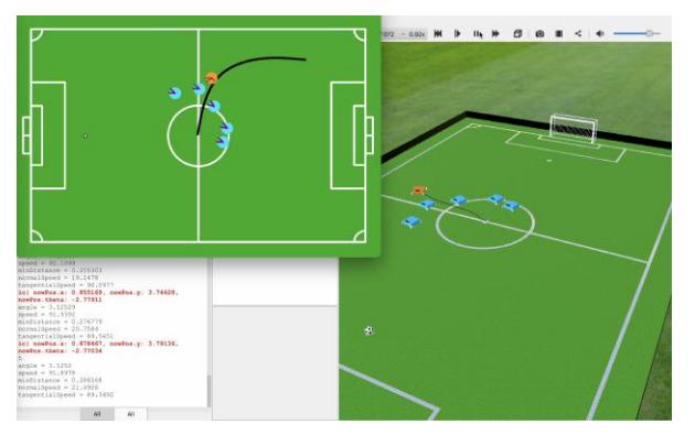
The high-level trajectory planner is based on the RRT* implementation provided by OMPL [6]. When the robots senses an incoming obstacle along its trajectory, we run its iterations for a set time duration allowing the robot to re-plan and converge to an optimum. Since the opponent teams robot coordinates are approximately known from the vision module in terms of a probability distribution, the necessary region is blocked out and marked as an obstacle in the occupancy grid. The environment most of the times remains sparse and the generated trajectories aren't extremely complicated as the target locations are chosen strategically for each robot. The generated trajectory is a set of points which is then smoothed by a C2 Cubic Spline Approximation. This trajectory is then sampled uniformly based on distance to allow the robot to follow using a piece-wise linear model with the maximum possible speed. The figure shows an example scenario where the above pipeline is running in the Webots simulator [4].
Communication and Data Layer
As we have mentioned several times already, most of the heavy lifting in terms of communication is done by ROS2 [3]. Several nodes are run on the Central server (NUC Enthusiast) that communicate with each other using data-types created manually for efficient processing. The code is written in C++. The image processing is done on the RPIs and the relevant data is transferred to the Main CPU over ethernet using the UDP Protocol. The CPU then performs sensor fusion to fuel the algorithms of Localization and Path planning. The low level control of the Motors is done using Arduino Microcontrollers which are commanded directly from the CPU using ESP32 code. Developing data transfer protocols for multiple bots and their efficient communication with each other and the base station is listed as future work to be done before the competition.
Conclusion
We conclude by reiterating that we are a new team trying to make our way into the challenging and highly competitive MSL. Due to constraints on manufacturing capabilities and budgets, we had to suffer numerous delays in the hardware-software integration, but given our insurmountable progress in the short span of a year, and still a few months to go for the competition, we are confident that we will be able to complete our first iteration of robots in time and would hopefully give other teams a good competition while learning immensely from the experience all the same.
References
- Hu, H.-N., Cai, Q.-Z., Wang, D., Lin, J., Sun, M., Krähenbuhl, P., Darrell, T., Yu, F.: Joint Monocular 3D Vehicle Detection and Tracking (2019)
- Lauer, M., Lange, S., Riedmiller, M.: Calculating the perfect match: An efficient and accurate approach for robot self-localization. In: Bredenfeld, A., Jacoff, A., Noda, I., Takahashi, Y. (eds.) RoboCup 2005: Robot Soccer World Cup IX, pp. 142–153. Springer, Berlin, Heidelberg (2006)
- Macenski, S., Foote, T., Gerkey, B., Lalancette, C., Woodall, W.: Robot operating system 2: Design, architecture, and uses in the wild. Science Robotics 7(66), 6074 (2022) https://doi.org/10.1126/scirobotics.abm6074
- Webots: http://www.cyberbotics.com. Open-source Mobile Robot Simulation Software. http://www.cyberbotics.com
- Hong Thai, N., Ly, T., Dzung, L.: Trajectory tracking control for mecanum wheel mobile robot by time-varying parameter pid controller. Bulletin of Electrical Engineering and Informatics 11, 1902–1910 (2022) https://doi.org/10.11591/eei.v11i4.3712
- Şucan, I.A., Moll, M., Kavraki, L.E.: The Open Motion Planning Library. IEEE Robotics & Automation Magazine 19(4), 72–82 (2012) https://doi.org/10.1109/MRA.2012.2205651 . https://ompl.kavrakilab.org