UM Croatia team description paper 2024
Filip Kuzminski, Petar Slaviček, Vedran Zović, Josip Dujić, Jaša Kocijan, Jan Hajsok, Antonio Ćuk, Matko Pribičević, Tea Kukec, Ana Vuković, Marija Vuković, Dijana Milek
Faculty of mechanical engineering and naval architecture University of Zagreb; University of Zagreb Faculty of Electrical Engineering and Computing; University of Zagreb, Faculty of Humanities and Social Sciences
https://www.udrugamehatronicara.com/
Abstract UM CROATIA is a student only team that started making MSL robots in 2022. Students are divided in teams that do software, embedded hardware and mechanical engineering and there is a marketing team that does fundraising for robot components and going to competitions. The team is focused on low budget design and education and does a lot of production in house. The main goal of the team is to allow students to work on cool projects and gain knowledge in mobile robotics and industrial systems.
1 Introduction
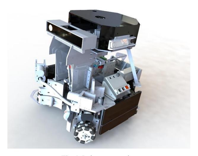
UM Croatia is finalizing robot design "UMbot1.2", oriented at low cost, low maintenance, safety and ability to play on any type of hard terrain. The robot is a 4 omni-wheel platform with mechanical kicking mechanism and advanced tactical mechanism for ball dribbling. The design is made in such way that it can be repurposed for functions other than playing soccer, just by replacing the upper portion of the robot.
2 Robot construction
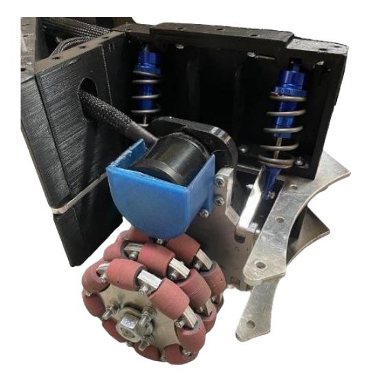
UM Robot is counstructed in three levels or platforms. Platforms are connected with 3D printed briges and walls with features that ease assembly. It's motion is achieved with 4 brushless DC Flysky motors which are connected to omniwheels via gear transmission with reduction of around 5. Omniwheels are produced in house, and are derived in three rows with 8 polyurethane wheels within one row. Every power module (Consisting of omniwheel, shaft, gear transmission and motor with mounts) is equipped with two dumpers with springs which are connected through clips between first and second level of the robot providing smooth motion of the robot and robust behaviour in high acceleration rates. The battery pack is at the center of the robot between first and second level and is also designed and manufactured in house. Between first and second level is positioned all the hardware for driving power motors and kicking and dribbling stepper motors along with power distribution. The third platform is the base for pyramidal construction on top of which are vision and computing systems. Third platform is also base for kicking and dribbling mechanisms.
2.1 Dribbling mechanism
The ball is maintained in robot possession with flexible rubber which has non-torsive wire inside of it. The rubber is connected to the shaft with clips and is rotated with brushless Flysky motor through belt transmission. The shaft is positioned with 2 bearings inside of the 3D printed housing. The housing is attached on the aluminum panel which is also used to mount motor and transmission. Whole assembly is connected on top of the third platform with bolts. The whole assembly can be adjusted in height depending on rubber length, friction and diameter to achieve optimal contact with the ball. Friction between ball and rubber maintain contact and the peripheral speed assures positioning and catching.
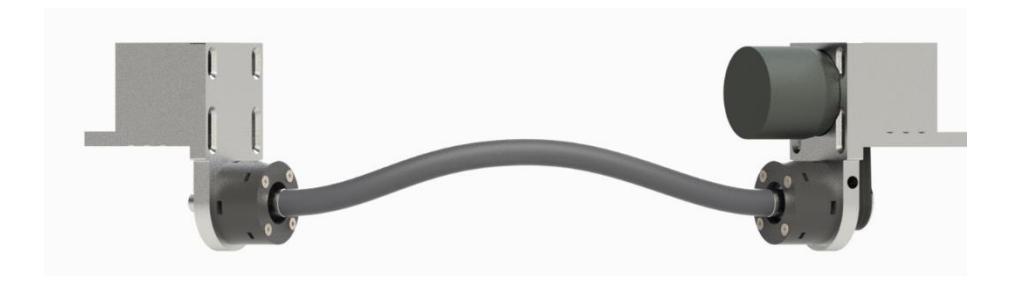
When the ball is outside of the robot reach and it is not detected with vision system, there is no signal to the motor driver and the rubber doesn't rotate. When the ball is within reach and there is a need to catch the ball, the rubber starts to spin and sucks the ball. When the ball is in possession, the speed of rubber is regulated depending on next desired move. It can rotate in both directions, so the ball can be rotated in neutral manner or towards robot center. When kicking of the ball occurs, rubber stops spinning and the kick is derived without resistance.
3 Robot electronics
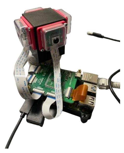
Robot uses an Nvidia Jetson Orin 32GB as the main processing unit. Robot consists of several modules, each controlling a different part of the robot. Every module on the robot is connected to the main processing unit via CAN bus. Preloading, position adjustment and releasing of the kicker mechanism is controlled by a custom shield attached to the ESP32 development board. Dribbler mechanism, and all four BLDC motors used to drive the omni wheels, are driven by VESC brushless speed controllers. Robot uses an XBOX Kinect 2.0 camera to aid in ball detection and has an omni vision system with four cameras that is used as the main object tracking system. Robot also uses Intel RealSense cameras together with IMU readings for spatial positioning. To power the robot, a custom Li-Ion battery pack in 3P12S configuration, nominal capacity of 9000mAh, nominal voltage of 44,3 V and continuous current output of 100A is used. The rest of the electronics is powered by stepping down the battery voltage using switch mode power supplies and buck converters.
4 Robot Software
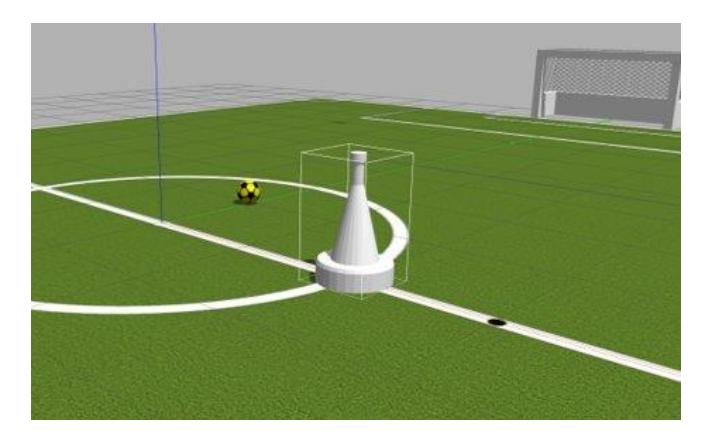
The robot software is built using Robot Operation System 2 (ROS2). This allows us to quickly prototype and experiment with different sensor modules and parts. Our system consists of three types of nodes: Input, Output and Control nodes. Each input (sensors, camera) has its own node that converts raw data to data formats used by other nodes. We use the TF2 system to track different transformations between our tracking camera, center of the robot, ball position, obstacles and robot target. To enable fast prototyping of our control loops and decision algorithms we developed a digital twin simulation of our robot using the Gazebo simulator. The main benefit of the simulation is that it allows us to use the same code that is in the physical robot in the simulation with minimal changes (velocities, PID control loops).
5 Conclusion
The UM Robot demonstrates a harmonious integration of mechanical, electrical, and software components. The three-level aluminum platform, powered by brushless DC motors and a sophisticated suspension system, ensures stability and adaptability to different loads.
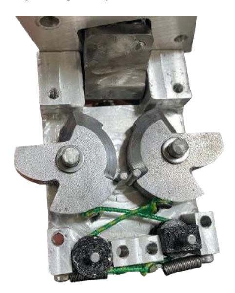
The dribbling mechanism, employing flexible rubber and a brushless motor, provides effective ball control. The unique kicking mechanism, mechanically derived, uses an aluminum leg and latex rubber for powerful kicks.
The ROS2 software architecture enables efficient prototyping, with sensor nodes capturing data from various sources. The T265 tracking camera plays a central role in coordinating sensor data, facilitating movement, obstacle avoidance, and decision-making.
The Gazebo simulator's integration expedites control loop and algorithm testing. The hardware description highlights a robust power distribution system, CAN bus communication, and safety features like the anti-spark switch.
The diverse hardware components, from movement and dribbler control to object tracking, contribute to the robot's versatility. In conclusion, the UM Robot excels in combining innovative mechanical design, precise electronics, and intelligent software, making it a commendable robotic platform for diverse applications.
References
- MSL Technical Committee 1997-2020: Middle size robot league rules and regulation for 2023 (2023), https://msl.robocup.org/wp-content/uploads/2023/01/Rulebook_MSL2023_v24.1.pdf